Because of the Thanksgiving holiday in the U.S., TI E2E™ design support forum responses may be delayed from November 25 through December 2. Thank you for your patience.

This thread has been locked.

If you have a related question, please click the "Ask a related question" button in the top right corner. The newly created question will be automatically linked to this question.

Any suggestion for an linux capable audio I2S ADC

Other Parts Discussed in Thread: TLV320ADC3101, PCM1862, PCM1808, TLV320AIC3104, PCM9211, PCM1865, PCM1861, PCM1681

Hi,

I am looking for a good Audio ADC with 96KHz and 24 Bit res, it must not be High-End in order to fit the costs. We need the I2S ADC to be linux compatible means, to have linux driver and devicetree setup instruction.

Any help is highly appriciated.

Bes regards,

Nils

  • Hi Nils,

    Take a look at the TLV320ADC3101, or the non-Mini-DSP enabled ADC3100.  They should fit your needs.  There are several publicly available drivers for these devices, but there will be some required modifications to match you exact kernel and processor implementation.

    There are many devices pushed into v 4.19.1:  https://git.kernel.org/pub/scm/linux/kernel/git/stable/linux.git/tree/sound/soc/codecs?h=v4.19.100

    There are many devices pushed into v 5.4.16:  https://git.kernel.org/pub/scm/linux/kernel/git/stable/linux.git/tree/sound/soc/codecs?h=v5.4.16


  • Hi Collin,

    thanks for your good feedback. That's clever to look in the codec list of the kernel ^^.

    The TLV320 is cool but I think it has a lot of function that we might not need. I found the PCM1862 very interesting, what do you think? Our goal is to create a vinyl player , have a look at the system.

    The PCM1862 has a better SNR and higher res for nearly the same price. We could use the filter front-end in our application as well as the Amplifiers. The Input of the PCM1862 is the Output of the RIAA amplifier circuit. The PCM1862 does not support I2S, right? Only Left alligned audio data?

    Thanks for your feedback.

    Best regards,

    Nils

  • Hello,

    PCM1862 is a good option, PCM1808 is even simpler if you're looking for really simple.  The PCM186x does support I2S, as does the PCM1808.

    Note that you may save some system cost by combining your ADC and line out blocks by using a CODEC.  Maybe the TLV320AIC3104 (Stereo in/out) would work?  There's a driver for it as well in both the repositories we previously shared.

  • Hi Collin,

    thanks for your feedback. I think I will use the PCM1808. It is simple and cheap and fit's my application :) I am using an TPA6130 as Head-Amp for some reasons.

    Best regards,

    Nils

  • Hello Collin,

    an other question regarding the PCM1808 you suggested to me. I think this ADC will be fine, we will use it with a tiny linux module (eq. raspberry pi). Will the PCM1808 will act as master or slave? So this will set who will generate the clock right?

    For receiving the Audio data we would need to add this device to the devicetree without I2C communication correct?

    Thanks,

    Nils

  • Hi Nils,

    The choice to configure the PCM1808 as the master or slave largely depends on how you'll be configuring the raspberry pi device and what else is on the bus.  Since you have multiple devices on the bus I previously thought you'd be operating the PCM1808 as the slave.  If you'd like to operate as the master then you'll need to supply an external MCLK, or use the XTAL circuitry shown on the EVM.

  • Hi Collin,

    I never used I2S before so I am a bit struggeling on the design decissions. Ok I think I would need to configure the pi (or other linux CPU) as Master and the PCM1808 as Slave. The Pi will generate the Masterclock, right?

    Like shown on the image, I have a line out driver that is connected to the I2S bus. Is this the right setup?

    Thanks,

    Nils

  • Hi Nils,

    Every driver/processor combination works a little different as far as what commands are required to send out the clocks, but in a standard build when configured as a 4-wire I2S bus master, the processor will generate the MCLK, BCLK, and WCLK signals and the PCM1808 will output the DOUT signal for the processor to receive.

  • Hi Collin,

    again thanks for your help!

  • Hi Collin,

    sorry for bother you again. We are currently testing the setup with rpi as master and PCM1808 as slave. We need to generate the Master clock (MCLK) from the rapsberry pi but we can not figure out how to do this, can you help uns with this? The I2S connection is fine to us but the mclk is missing. we could use the GPCLK0 for generating a clock signal but is this the correct approach?

    Thanks and best regards,

    Nils

  • Hi Collin,

    sorry for asking you again in this thread, maybe I should start a new one. After some research we decided to go with the PCM1862 instead of the PCM1808. I think this is compatible with the raspberry pi using the device driver from your links and this ()

    • As my RIAA amp gives me an output of ~3V the 2.1V RMS input of the stereo ADC is ok right?
    • The rapsberry pi is not able to generate the MCLK signal so the PCM1862 will be the master, do we need to change something in the driver/device tree? So I also have to generate the Clock signal on-board like done on the evaluation board correct?
    • I am using a single ended input to the ADC from my RIAA output. Can I use the evaluation board to test my application ? How should I connect it?

    Thanks for your help!

    Best regards,

    Nils


  • Hi Nils,

    We are not Linux driver or Rpi experts so we won't be able to provide much assistance with the device tree configurations and you may need to dig in and try different configurations or look for a similar implementation in the community.

    1.)  Assuming you meant 3Vpp, then yes, this will be within the 2.1Vrms inputs of the PCM186x.  Use an external AC coupling capacitor, similar to what's done on the EVM.

    2.)  Yes, you'll need to generate an MCLK, either through a reliable timer output on your processor, or an oscillator/crystal circuit.  It's really difficult to provide guidance on the device tree and driver as this is outside of our expertise but the desired configurations are common and should be supported, we just don't have the expertise to directly instruct you how to do it.

    3.)  Yes, connect the input signal to the EVM either through the RCA connections or directly afterwards.  You'll then need to disconnect the device from the PCM9211 and I2X controller by removing some components and then by wiring in your external processor.  This is not the easiest thing to accomplish as the EVM is primarily designed to demonstrate the performance of the PCM1865 while interfacing with an audio analyzer or by streaming audio back to the PC through the I2X board. 

  • Hi Collin,

    I noted your advice and designed a schemaic based on the PCM1861 (Hardware controlled). I think the PCM1862 give us more settings but we I think it makes things more complicated.

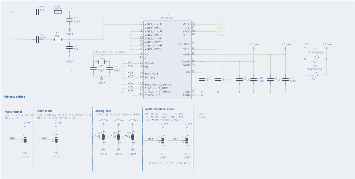
    I have attached an image of my PCM1861 circuit with notes how I would think the settings would look like.

    The important thing is, that the PCM186 is the I2S Master, as the RPI is not able to do this. I use ADC 1 in single ended configuration with 96kHz sampling rate, correct? I added this Crystal ()

    The MDX settings are from the datasheet.

    What do you think about my circuit? Thanks again for your feedback and sorry for that many noob questions.

    Best regards,

    Nils

  • Hi Nils,

    The connections and usage of the HW controlled devices like the PCM1861 are pretty straight-forward making them easier to use than the digitally controlled products.  In the schematic, the inputs, power and decoupling look good.  We would recommend some series resistance (~22-33Ohms) on the MCLK, BCLK, and DOUT lines to help w/ ringing/oscillations but outside of that we agree this looks okay and the unused inputs on this device can float.

  • Hi Collin,

    thanks for you circuit tips. I will add the resistors to the I2S lanes. Is my clock clalculaion correct and is the (ABM3-24.576MHZ-D2Y-T) crystal with the 18pF fine for the PCM1861?

    Thanks again for your support! This is the reason I am using products from texas instruments!

    Best regards,

    Nils

  • Hi Nils,

    The ABM crystal is the correct frequency and you'll use a 256*fs divider setting to take the 24.576MHz clock down to 96kHz sampling rates.  We'll leave it to you to verify the exact components around the crystal and if you need 2x18pF capacitors, or a total impedance of 18pF (the two are usually considered in series from the crystal resonance standpoint.).

    The PCM186x datasheets specify a typical load capacitance of 15pF so an 18pF crystal should work well.

  • Hi Collin,

    thanks :)

  • Hi Collin,

    Just another question, I designed my circuit board like shown in the schematic above but I ordered the wrong ADC. i ordered an PCM1862 instead of the hw controlled PCM1861. Is there any way to use my circuit with the places PCM1862?

    Thanks and best regards,

    Nils

  • Hi Nils,

    I recommend trying to acquire the PCM1861 as your schematic was designed for the HW pin controlled version.  Otherwise you'll need an I2C master to program the PCM1862 registers.  They are pin-to-pin compatible outside of the digital interface section (HW vs. I2C).

  • Hi  Collin,

    today I got my PCM861 replacement and I changed the wrong placed PCM1861. SO now a PCM1861 is placed on my hardware with the schematic shown above. I maybe had some missunderstanding but I thought in this configuration (Master mode 11) i get an Master Clock output from the ADC?

    I get output following signals :

    - DATA pin provides some data output

    - SCLK provides a 6.144MHz signal (Is this correct?)

    - LRCK provides a 96.01 kHz signal (Is this correct?)

    - MCLK that should act as an output as it goes to the line out chip has no signal

    Did I understand something wrong? I choosed the PCM1861 as it should be able to act as master and to provide a master clokc right?

    Thanks for helping!

    Best regards,

    Nils

  • Hi Nils,

    The PCM186x devices, like most Audio device master ADC/CODEC devices will still require a low-jitter stable, MCLK input to then generate the BCLK, WCLK, and DOUT outputs back to the host processor.

    On the EVM this is shown with a 24.576MHZ oscillator/XTAL design.  

  • Hi Collin,

    I provide the 24.576MHZ clock through an external Crystal oscillator using X0 and XI. But I maybe missunderstood something. I thought, when using an crystal oscillator the PCM1681 will generate the MCLK signal for other devices as well. So in order to make it work with my schemativ provided above, I need to remove the Crysta from XI/XO and have to provide a CMOS Clock with 25.5760 MHz to SCKI right?

    Thanks for your help,

    Nils

  • Apologies, I thought I'd replied to this but maybe it didn't post.

    I misstated some things slightly above and was confusing this device for another where the SCKI behavior is implemented differently.  For both the HW and SW controlled devices in this family, the SCKI signal is always an input.  If you need to operate in a 4-wire master mode, then you'll need to use one of the SW controlled variants and enable the "SCK_OUT_TO_GPIO" control setting to output the SCK to a GPIO.

  • Hi Collin,

    thanks for your response! We solved it by adding a CMOS oscillator on the circuit board as we are using the hw controlled chip.

    However, thanks for your support in this development case!

    Best regards,
    Nils