This thread has been locked.

If you have a related question, please click the "Ask a related question" button in the top right corner. The newly created question will be automatically linked to this question.

LM5160DNTFBKEVM: Problem for Flybuck design on negative primary Vout setting

Guru 19685 points

Part Number: LM5160DNTFBKEVM
Other Parts Discussed in Thread: LM5160

I trying to design below specification Flybuck DC/DC in the restricted to use LM5160 and 1:1.3 transformer.

⇒Vin: 24V, Vout_iso: 18V / 200mA, Vout_pri: -14V

The reason for Vout_pri set negative voltage is keep Duty cycle less than 50%. (When Vout_pri set positive 14V, it is over than 50% and not recommended)

But Vout_iso is output Vin ×1.3, not to became 18V. 

Can negative Vout_pri setting make isolated output solution?

If yes, please let me know about any reference design or possibility to become Vin ×1.3.

My solution is based on LM51600DNTFBKEVM, with primary side changed Vout ⇒ GND and GND ⇒ -Vout_pri.

And, remount default transformer to 1:1.3 transformer, and changed any external components (500kHz setting and feedback resister for -14Vout_pri)

※Reference material is below

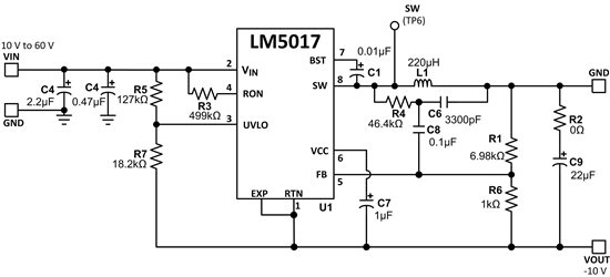
Other Parts Discussed in Post: LM5017 The synchronous buck converter IC can be used in inverting buck-boost configuration by simple modifications to buck converter schematic as shown in Figure 1a and 1b…
By in Technical articles > Power management

Best regards,

Satoshi

  • HI satoshi:

    you configuration is right, what's the second the output voltage vs secondary load?

    for flybuck, the no load voltage will be higher than you setpoint, especally in higher fsw. the full load setpoint will be lower then your setpoint, due to the leadage inductacne of transformer.

    Thanks

  • Hi Daniel

    Thank you for fast reply,

    When Vout_iso become Vin ×1.3, load is 0A.

    Full load (200mA) is become about 28V, but still far from the Vout_iso: 18V.

    Please let me know about two points for reach the 18V;

    ・Is higher fsw effective to reach the set point of Vout_iso, correct? 

    ・For Flybuck solution, is isolated output voltage fluctuate to a certain extent? 

     If there any idea for suppress fluctuate, please let me know.

     (Is primary side add to load current effective to Vout_iso fluctuate?) 

    By the way, request spec is 18V ±10%.

    Best regards,

    Satoshi

  • Hi Satoshi:

    can you help check the transformer name, you may connect wrong name of transformer which deliver Vin to output, so that the Vo~=1.3XVin-Vd.

    1 higher fsw will make the load regulation poor and need larger dummy load than lower fsw

    2. I think voltage fluctuate means voltage ripple,  it can be reduced by put larger capacitor or you can add a small LC filter at output

    Thanks

  • Hi Daniel

    Thank you for advice, I will adjust tomorrow.

    Transformer name is Wurth: 750313638.

    Above transformer is remount on LM51600DNTFBKEVM's default transformer.

    The reason for use 750313638 is trying to make more low cost and size solution.

    Best regards,

    Satoshi

  • Hi Satoshi:

    Do you need 5000V isolation between primary and secondary and 340uH inductance?

    When you choose the transformer, pls make the leakage inductance as small as possible. use proper transformer inductance and isolation voltage can make the leakage inductance small.

    small inductance can improve secondary load regulation.

    Thanks

  • Hi Daniel

    Yes, our customer need 5000V isolation.

    I confirming transformer's leakage inductance to manufacture, please wait for a little while longer.

    I adjusted any point, at first Vout_pri and Vout_sec was output. 

    But Vout_pri was voltage drop by time. (Vout_sec is drop tracking with Vout_pri)

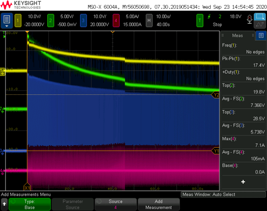
    Long time waveform (10 sec / div) is attached below, please let me know about any reason and measure for prevent output voltage drop.

    ※CH1(Yellow): Vout_pri (it shown on reverse polarity the reason of probe connection ), CH2(Green): Vout_sec, CH3(Blue): Vsw_pri, CH4: Isw_pri

    【Additional information】

    ・Vout_pri is no load condition

    Best regards,

    Satoshi

  • HI 

    what is the secondary load condition? is Channel 4 is 5A/div?  pls check whether the Isw_pri trig the OCP

  • Hi Daniel

    I answer your question below; 

    Secondary load is no load, but 50mA~200mA load was also voltage decrease.

    Yes, Channel 4 is 5A/div, peak current became too large.

    Isw_pri triggered OCP.

    Is these issue large effect by transformer spec? 

    Best regards,

    Satoshi

  • HI

    Customer can use a small inductance transformer to see whether the issue can be fixed to verify it is transformer issue or not

     From Vo_pri and Vsec_pri waveform, it looks match Vo_sec=Vo_pri*1.3, but the attached waveform can't see the each cycle clearly. 

    You need use a good secondary diode with lower leakage inductance. 

    Thanks