This thread has been locked.

If you have a related question, please click the "Ask a related question" button in the top right corner. The newly created question will be automatically linked to this question.

PTH08T255W: PTH08T255W tech issue

Part Number: PTH08T255W

Hi TI expert

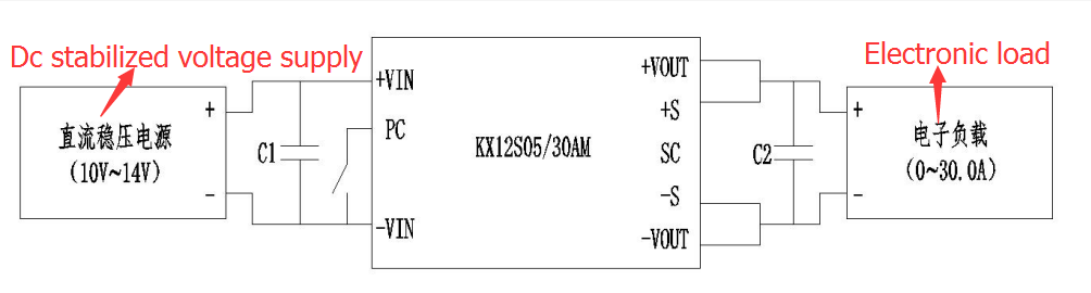
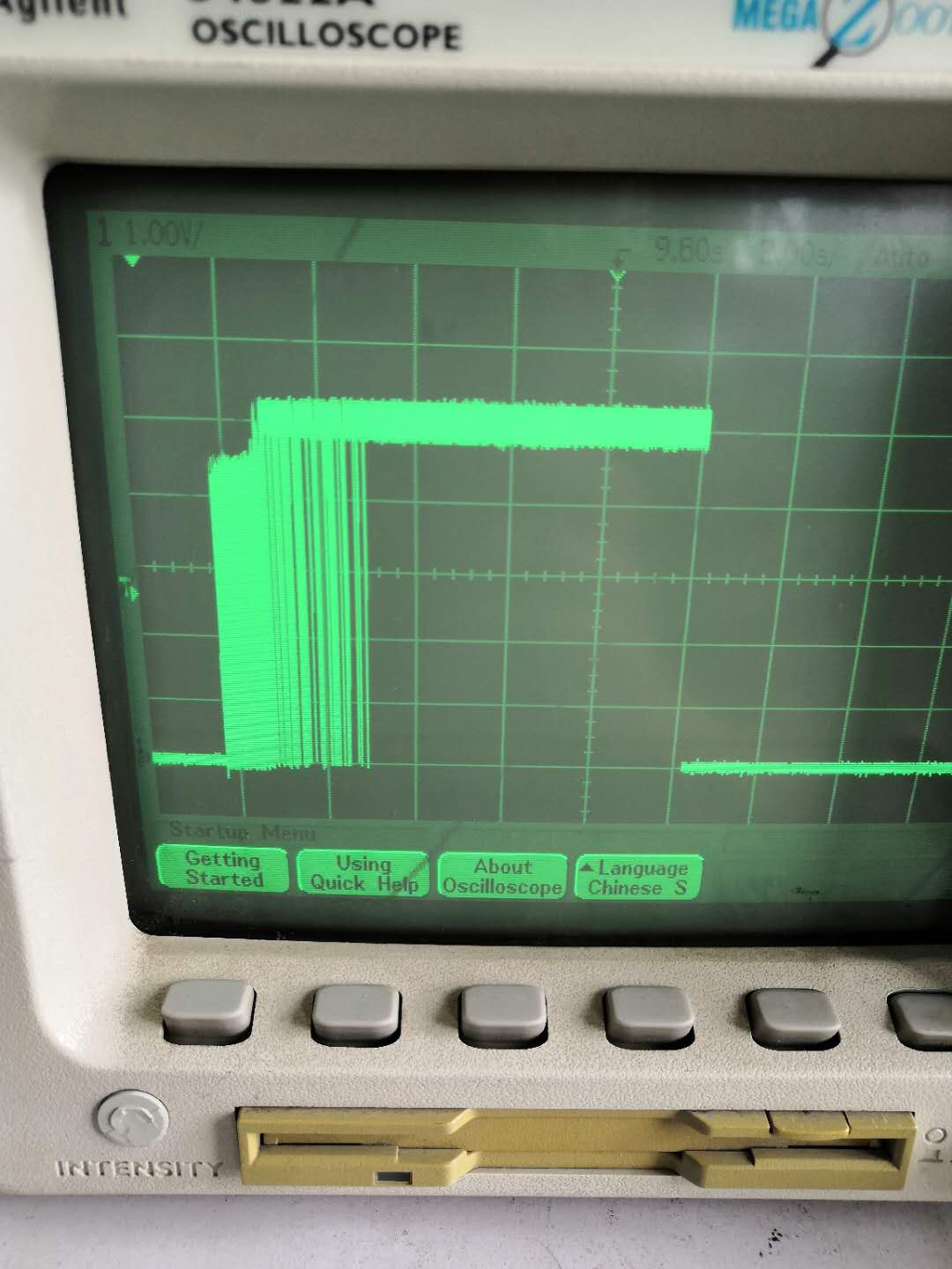
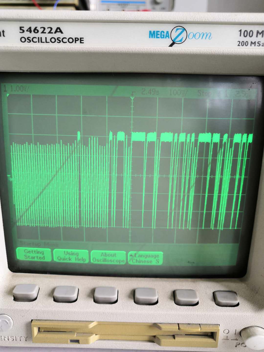
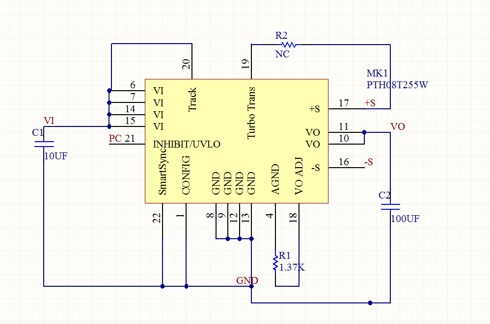
We have bought 5pcs of PTH08T255W, When input +12V and output +5V 30A under -40 ℃, the on load output voltage flickers about 2V.

Please help to check the reasons.

Best regards,

Thomas

  • Hi Thomas,

    The part works fine under other temperatures?

    Can you please share schematic and oscilloscope capture of the flicker to start?

    Regards,
    Kris

  • Hi Kris

    It works fine under other temperatures.

    Please find below schematic and oscilloscope capture of the flicker.

  • HI Thomas,

    So the PTH08T255W is used within the KX12S05/30AM block you have pictured above? Can you share the internal schematic of that block?

    Can you please share the input and output capacitor part numbers and quantity?

    Kris

  • Hi Kris

    Please refer as below internal schematic capture and PCB file.

     0882.PCB.zip

  • Hi Li,

    Do you have input and output cap beyond what is shown in your schematic? The PTH08T255W datasheet mentions minimum 1000uF input capacitance (see datasheet p.9) and minimum 1000uF of output capacitance (see p.10).

    Kris

  • Hi Kris

    The input and outpput capacitance we set up are both 1000uF.

    Thomas

  • Hi Thomas,

    Thanks for confirming the input and output cap are meeting the datasheet-mentioned minimums.

    You mentioned in the original post of a 2V flicker, but if I read the oscilloscope screenshot, it looks like the output is toggling between 0 and 5V.

    Can you please take the same waveform with VOUT, VIN, and INHIBIT/UVLO signal included?

    What is the load current during this test? Is it a steady state load when you also go down to low temperature?

    Regards,
    Kris

  • Hi Kris

    At that time, about 2V flickered. We were looking at the voltage displayed by the electronic load, which may not be very accurate. The last oscilloscope photo only lasted about 1 hour at low temperature. It can be seen that the front-end output voltage jumps around 4.5V for a certain period of time, and then rises to 5V.

    The most important thing is to ask if there are any problems with this mode of application, including circuit layout, etc., which will affect the parameters of the module at low temperature. Because we have read the module information and introduced - 40 degrees can work, we want to determine whether it is our peripheral circuit problem.

    Best regards,

    Thomas

  • Hi Thomas,

    The module should work at -40C and I don't see any obvious issues with the schematic and layout, outside of potential concerns mentioned in questions below:

    1) How far away the remaining input capacitance is from the module? Since the schematic and layout provision only for the 10uF C1, I assume the rest of the 1000uF is some distance away from your board. If they are far away they may not be providing sufficient input decoupling and the input at the module pins may have significant ripple.

    2) How long are the cables connecting the module to the load where you connect the S+ and S-?

    3) Is the additional output capacitance at the remote load, or near the module output pins?

    4) Is there a difference in -40C behavior whether you tie S+ and S- directly to Vout and GND at the module versus connected to your actual load? I just wonder if there is some stability issue with your actual remote sense connection

    Regards,
    Kris

  • Hi Kris

    Please refer as below answers.

    1) The 1000uf capacitor is about 4cm away from the module, which belongs to the test external capacitance.

    2) The distance between S + and S - and output pin is about 5mm, and the wire from module to load is 1 meter long.

    3) Additional output capacitance is connected to the output pin of the module.

    4) In our test, S + and S - are directly connected with Vout and GND near end, and then connected to the electronic load through about 1 meter wire. We are connected in this way at room temperature and high temperature. Both normal temperature and high temperature are qualified

    Best regards.

    Thomas

  • Hi Thomas

       As Kris mentioned, having the 1000uF input and output capacitors close to the module is critical. Why are they far away from the module?

    Regards,

    Gerold

  • Thomas,

    Thanks for the info. My main suggestion would be to, If it is possible, try moving the input capacitors closer to the module input pins instead of 4cm away. See if that affects the -40C behavior.

    If the circuit is working fine at room and high temp, I do not think there is an obvious reason -40C would show any issue, but in general in any buck converter, proper input decoupling is very important for proper operation.

    Kris

  • Hi Kris

    The capacitor lead is shortened from 4cm to 5mm and 2pcs are tested  at - 40 ℃.  The output is still the same as before, about 2V flicker, without any improvement.

    Please help to check.

    Best regards,

    Thomas

  • Hi Thomas,

    Do you mean two boards were tested at -40℃ with same result?

    Let me also consult with some colleagues for their input as well, and get back to you.

    Regards,
    Kris

  • Thomas,

    My colleague also asked for an oscilloscope capture with VOUT, VIN, and INHIBIT/UVLO signal . I asked for this a few replies back but it doesn't appear as though you provided it. Is it possible for you to provide this?

    How are you setting and monitoring the temperature in your test setup? Just wondering if any chance that the temperature is not well controlled and perhaps temperatures are going well below -40C.

    Regards,
    Kris

  • Hi Kris

    Thank you for your replying.

    The test environment is a general low-temperature test box, and the temperature is the temperature displayed on the display screen. Then we regularly conduct the temperature calibration test, but the test waveform results are still the same as before.

    Please help to check.

    Best regards,

    Thomas

  • Thanks, Thomas. Can you please confirm your comment before -- you have tested two different units/boards at -40℃ with the same flickering observed?

  • Hi Kris

    As your suggestion before, we have changed that the capacitor is shortened from 4cm to 5mm and tested 2pcs.

    But still at 2V flicker under - 40 ℃.

    Please help to check.

    Best regards,

    Thomas

  • Thomas,

    It will really help to see a scope capture showing VOUT, VIN, and INHIBIT/UVLO signal (PC on your schematic) during this -40℃ test. I do not have any other debug suggestions at this point.

    Regards,
    Kris

  • Thomas, will you be able to get the requested scope capture? -Kris