This thread has been locked.

If you have a related question, please click the "Ask a related question" button in the top right corner. The newly created question will be automatically linked to this question.

TPS92518HV: TPS92518HV dies in Shunt FET operation mode

Part Number: TPS92518HV
Other Parts Discussed in Thread: TPS92518

Hi,

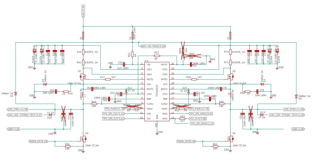
we have done a design with 2 altmost identical TPS92518HV (i.e. 4 channels). The design is closely related to the EVM schematic, see below.

When activating the shunt FET, the TPS dies exothermically and sometimes also the Shunt- or the TPS-FET, even at low LED currents ~200 mA and VCC <= 30V.

To prevent overshoot, we have implemented all suggested measures.

The design should be able to handle at least 5 amps LED current, that's why we used a different inductor type (same L but higher current) and different MOSFETs (NVTFS010N10MCL) as used in the EVM schematic.

Any ideas why that happens?

Regards

  Roland

  • Hello Rolland,

    A few things.  Do you have the Toffmax set at a high value?  Did you calculate what it should be?  the reason is the if Toffmax is set too low the current will increase, ratchet up, as the shunt FET is on.  The TPS92518 has a minimum on-time so the off-time needs to be long when shunted since the voltage across the inductor is minimal (freewheel diode, IR drop of the inductor and the IR drop of the shunt FET).

    The other thing is the Vout diode back to Vin.  If there is inductance to the LED load Vout can overshoot and cause damage to the TPS92518, this is in the datasheet, page 9, section 3.4.3.  There isn't a location on the EVM for these diodes.  There is also an RC to Vout (which should have the values changed) that can be added however I would still go with the diode to Vin.

    Do you have issues if your shunt time is very short such as a few microseconds?  This would prevent the current ramp up if the issue is Toffmax but would still fail if Vout overshoot is causing the issue.  You can also watch the inductor current or current before the shunt FET to see if it is increasing or not.

    Best Regards,

  • Hi Irvin,

    thanks for the quick answer!

    Toffmax had been calculated to 80. Neither 255 nor 80 made a difference. Toff is 43.

    The freewheel diode are also in the design as well as the RC to V_LED (10k, 100 nF). The is no overshoot according to the measurements.

    As you can see the schematic closely follows the EVM schematic with the shunt extensions. 

    The 100 µH inductor is a big one (9A) with a low DC resistance.

    The strange thing is that a shunt PWM of 1 kHz and lets say 30% duty cycle does not kill the TPS but as soon as the duty cycle is close to 100%, the TPS dies and sometimes also the MOSFETs. The power supply has a current limit set to 0.2A, however the energy stored in the power supply capacitors seems to be enough to blow the parts.

    The next thing is to measure SW1 and the inductor current. To do this I have to wait until the prototypes (4 boards) get repaired.

    Is there anything from the schemtic below which could cause the problem?

    Thanks again and best regards

  • Hello Roland,

    Could you let me know what diodes (D2, D3, D15, D19) as well as the inductor you are using?

    I think what might be going on is being caused by R49/C64 and R58/C72.  Try changing C64 and C72 to 220 pF or something around that.

    What is your Vin range, 30V is stated above?  What is Vout?

    VLED1 and VLED2 determine the off-time.  If you are shunt FET dimming at high duty cycle the RC is filtering the actual output voltage making the VLED high when the output is shunted.  This will cause a shorter off-time which could result in run away current.

    Best Regards,

  • Hi Irwin,

    thanks again!

    D2, D3, D15, D19 are ONSEMI NRVTSA3100ET3G diodes (3A continuous). As we are targeting 5-6A, we will probably replace them with a diode capable of more current. However for the moment the DAC setting is 31 so the peak current is ~0.5A which should be ok for the diodes.

    The inductor is PA4349.104ANLT from Pulse Electronics (100 µH, 9A saturation).

    Vin is in the finaly device constant 48V from a mains power supply. We've tested with 30V lab power supply as the "exothermic effects" we less extreme as with the first tests of 48V....

    Vled is ~35V, however the LEDs light up already at 30-32V.

    By the way, what happens, wenn the peak current is never reached? I suppose the FET will be on forever. Correct? And when in this condition the shunt FET is closed, the peak current will be reached and the off cycle will begin? So this should be safe also.

    I calculated that the R49/C64 low pass delay would be around 0.7*R*C = 700 µs and wondered if this is fast enough. As the EVM manual states stat shunt FET dimming should use this values, we designed that in.

    What is still unclear to me is in case the above mentioned RC is the root cause, why would that kill the TPS? From my limited perspective, I would think this would kill the FETs and maybe the TPS because the killed FETs have shorts to all pins. However it looks ilke that I have also situations in which only the TPS died but not the FETs (at least the FETs do not have shorts in this case).

    Dou you have an explanation for that?

    As soon as we get the repaired board we will test with C64/72 220 pF.

    Best regards

      Roland

  • Hello Roland,

    If the peak current is never reached the MOSFET will just stay on.  Note that the TPS92518 regulates peak current so there can be a very small window where the actual LED current is higher than the operational average.  This is when the MOSFET is on and the current is just below peak trip threshold.  Since the inductor is between the TPS92518 MOSFET and the Shunt FET closing the shunt fet will cause the current to rise at V = L *(di/dt) where V is Vin.  This is slow compared to the peak current threshold detect so it will operate fine.

    That portion of the schematic has the 10 Kohm as a place holder, the schematic on the next page shows zero ohms.  Unfortunately 0.1 uF is not correct either because the actual resistor value would need to be much lower to make sure VLED is representative of the actual output voltage.

    There can be a few things going on regarding a failed TPS92518.  One is the output is overshooting during shunt FET dimming and getting back to the TPS92518.  Another thing I didn't mention before are your fuses.  Fuses are not shorts, they are resistors and inductors (to some extent).  This means the Vin to the IC and the Vin to the power stages aren't really connected with a low impedance connection.  I would try to make sure that the Vin to the TPS92518 and the Vin to the MOSFETs are connected via a low impedance path.  The MOSFET is referenced to the capacitor banks, the Gate drive to the MOSFET is referenced to the TPS92518.

    As for the RC issue.  If that RC filter is slow the VLED will see VLED for a while when the shunt FET is turned on.  This determines the off-time.  It will be much shorter than it needs to be possibly causing the current to ratchet up due to minimum on-time.  When you mentioned shunt FET dimming at 30% was okay but higher duty cycles had issues it seems that the RC voltage would be much lower at 30% duty cycle causing a longer off-time and at higher duty cycle the off-time would be shorter.

    Is your LED load far from the driver, connected with wires creating some inductance between the driver and LEDs?  Does teh driver work fine without shunt FET dimming?

    Best Regards,

  • Hi Irwin,

    thanks again.

    V_LED lowpass 10k / 0.1uF: Ok, we will change this to 10k/ 220pF. Or do you recommend 0R and 220 pF? 

    Note: We have testet earlier with the modified EVM (for shunt PWM) and did not change the 10k, but left unintentionally the 0R and 0.1 µF in and this works also without problems even in shunt FET dimming mode.

    Fuses: Ok we will try to change that. The TPS 2.5A fuse is a security feature as the TPS has small PCB traces not withstanding 7.5A or more. However as mentioned, I checked potential overshoot at the fuse of the TPS with the oscilloscope and we have indeed 2 TPS on our board. The other TPS never died when the first one died. As they are powered over the same 2.5A fuse, I think in case there would have been an overshoot, both TPS would have probably died.

    Indeed the LED is ~20 inches away from the board, but the same situation created no problem with the modified EVM (but 0R instead of 10k).

    The board works fine with PWM dimming, only shunting kills.

    So from my perspective, it looks like the RC problem with the wrong C and or wrong R could be the root cause.

    Tomorrow we hope to get the TPS and then the boards should be repaired quickly.

    So could you please check the RC again: 10k 220 pF or 0R 220 pF?

    Best regards,

  • Hello Roland,

    Either is probably fine.  The 10K/220 pF would still protect the VLED pin.  You could even leave the 10K and just remove the capacitor.  This would still limit the current if VLED overshoots.

    With PWM dimming the output isn't shorted out so if it is related to off-time being to short because of the RC regular PWM wouldn't fail.

    Good luck.

    Best Regards,

  • Hi Irwin,

    thanks.

    After tests with a repaired PCB: The problem cause was the 10k / 100 nF lowpass. Changing C to 220 pF works. Maybe Ti should correct the EVM Shunt FET PWM dimming add-on instructions accordingly.

    Best regards