This thread has been locked.

If you have a related question, please click the "Ask a related question" button in the top right corner. The newly created question will be automatically linked to this question.

BQ51013B: Coupling not sufficient to enable charging

Part Number: BQ51013B
Other Parts Discussed in Thread: BQ51013

Hello,

I am using a Wurth 760308101219 receiver coil and the below schematic:

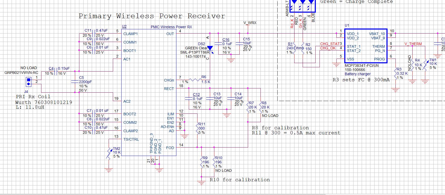
This schematic worked well when I modified an Adafruit 1901 receiver module with this coil and resonant capacitor values.  I have now implemented the design onto a custom PCA.  I am able to initiate charging if I get the coil extremely close to my transmitter, basically touching, but the charging does not stay on.  My Vrect seems to be too low, only reaching ~1V.  I am seeing the communication packets come through, so it looks like the IC is functioning and attempting to charge, but isn't coupling well enough.  

I have very limited equipment for testing values, I wanted to know if I would most likely need to increase or decrease my resonant values, or if the issue is more likely my COMM capacitor, maybe needing to increase it to 47nF? The case this will be installed in will alter the environment, so that's another reason I'm looking for a more qualitative suggestion, like increasing or decreasing a specific value.  I know my coil is small, it had to be for my dimensions, so I need to optimize my values, I don't care much about efficiency.

I'm charging a small battery at low current, do you have any suggestions?  I believe I need to increase my voltage rating for my series capacitor, but I don't think that's what my issue is right now with the coupling.

  • Hello

    The Wurth 760308101219 is 15mm round with free air inductance of 11.8uH.  As you noted smaller coils have a lower coupling factor and will make start up difficult.  To off sent the lower coupling factor a higher L will help, recommend trying to double this coil value.  Wurth also has a 760308101303 this is 47uH but 26mm round.

    Coil tuning looks OK.

    The Comm caps can be increased but this will only help if the start up ping is increasing voltage at RECT pin above 2.7V and you consistently see RX sending packets.

  • So the primary issue I will have with this coil is its size?  Increasing the series Cap won't help boost the voltage? I am looking at a couple Wurth coils, one the 47uH, and one the 26uH.  I assume to test these I will need to change my tuning values, or do you think they will be close enough to give me an initial readout?

  • So the primary issue I will have with this coil is its size? --- Yes, coupling factor drops with coil diameter, above 20mm works, below 10mm I have not been able to get to work.  Between is a gray area

    Increasing the series Cap won't help boost the voltage?  --- Not enough, only minor increase.

    I am looking at a couple Wurth coils, one the 47uH, and one the 26uH.  I assume to test these I will need to change my tuning values, or do you think they will be close enough to give me an initial readout? --- I recommend retuning

  • Thank you Bill, 

    I tried with both the coils I mentioned, in both cases I get immediate start-up on both my Qi transmitters I use for testing. My CHGn signal drops and turns on my indicator LED.  What I am finding though is that in both cases after about 15-30 seconds, sometimes less, the charging stops though my CHGn LED remains illuminated.  Would this be a case where I'm needing a boost in my communications to keep them stable?  I'm not sure why I would see success for 30 seconds then the charging stop but the voltage remains. I reduced potential current draw from the charger IC to 200mA, that was the only other change made aside from retuning the coils.

    I adjusted my comms capacitors to 47nF.  That seemed to make my connection much more stable with both coils.  I removed the batteries I am trying to charge and I verified that I get the charge indicator lights I expect from my charger, when I turn on the LED at the end of the chain I see that RED charging LED. When it is off and I connect to the TX I get a flashing green from the charger and a steady green from the CHGn LED.  It appears that I'm able to make a solid connection, until I try drawing power from it, and seemingly only when I get above a certain current level. I am still experiencing the phenomena where the system will indicate it is charging the batteries for several seconds, then I get a break in my connection and my TX is indicating an unspecified error.  Any ideas why pulling current is breaking my connection and how I can mitigate that?

    Thanks!

  • Hello

    I suspect this is FOD fault. 

    For FOD the power sent by TX to RX must match power the RX reports back to TX.  Missing power is loss and if it is too high a fault is set.

    Try increasing R-FOD so the RX reports more power back to TX, this is R9 (R10).  Try increasing the value to 300 ohms as a test. To keep current limit point the same reduce R11. 

  • Hi Bill,,

    Thank you for that response, that makes a lot of sense and I wouldn't be surprised if these values were causing issues in my set-up.  

    I will try your suggestion, however I wanted to note that between communications I was looking for processes that would shut down power transfer after a period of time; I have an NTC connected to the BQ51013, and I replaced this TS/CTL connection with a 10k resistor to ground to pull out the NTC signal and simply ground the line. 

    Across four boards on two different transmitters and two different coils this has allowed my system to continue charging, so far indefinitely, I'm testing a longer cycle now to see if I get to fully charged.  I have an IR temp gun I've been using to monitor IC temps and nothing is getting anywhere close to limits, hanging out between 30 and 40C after charging for 20 minutes.  

    If the problem were an FOD issue, I would not have expected this modification to solve the issue, is that an incorrect assumption?

  • Hello

    Do you have a group of devices that work and others that do not work?

  • Hi Bil,

    No, apologies for any confusion.  I have 4 boards, 2 are using the 19mm coil and 2 are using the 26mm coil.  All four were exhibiting the same behavior of maintaining a charge for a short period then shutting down. All four are now operating correctly after changing the TS/CTL NTC to a 10k resistor on both of my transmitters.

    Thanks!

    Adam

  • Hi Adam

    This is pointing to a thermal issue with the board.  Also the NTC could be the wrong type for your application.

    Thermal rise of the device can be caused by several problems, the below FAQ may help.