Hi,
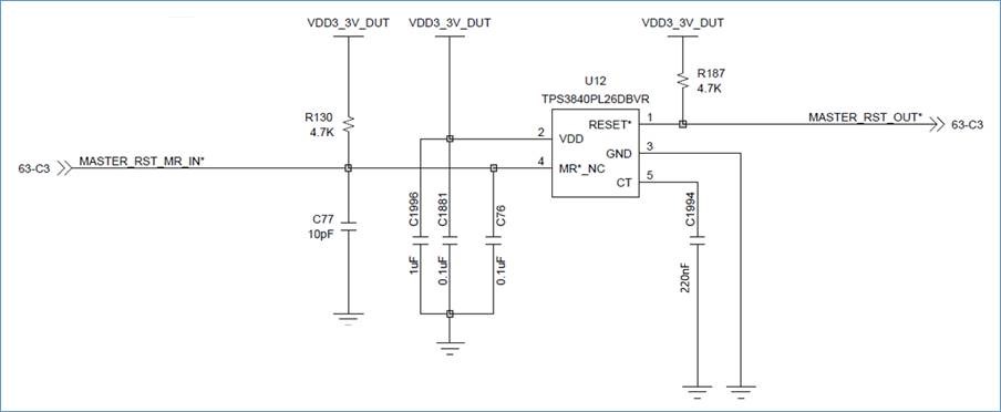
One of my customers is currently using TPS3840PL26DBVR and they reported a problem with the reset output signal.
They asserted MR input but the reset output was asserted only for about 1us.
Please check their schematic and signal captures and give advice.
- Customer schematic
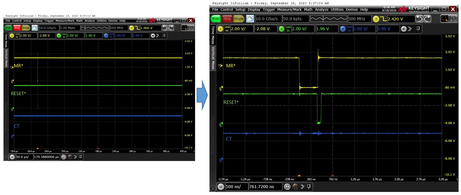
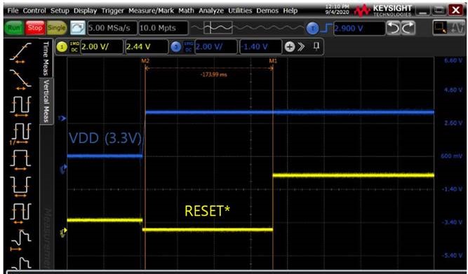
- Signal capture #1 (Reset output and VDD)
The following is signal captures of reset output and VDD.
There is no problem with reset output signal by VDD.
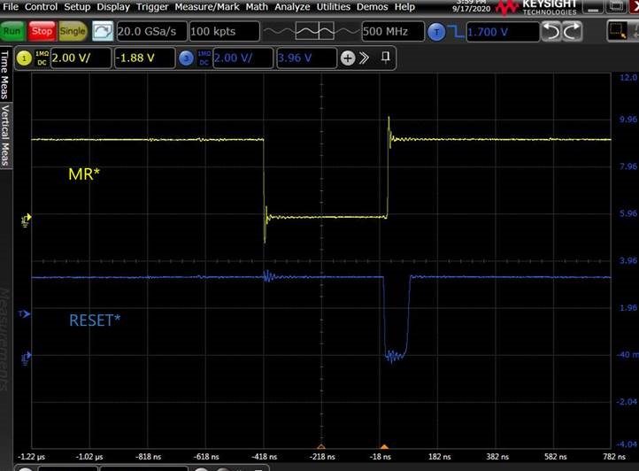
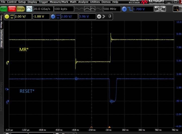
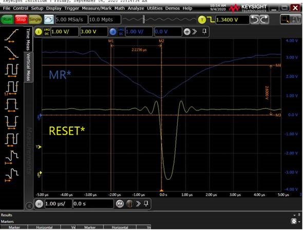
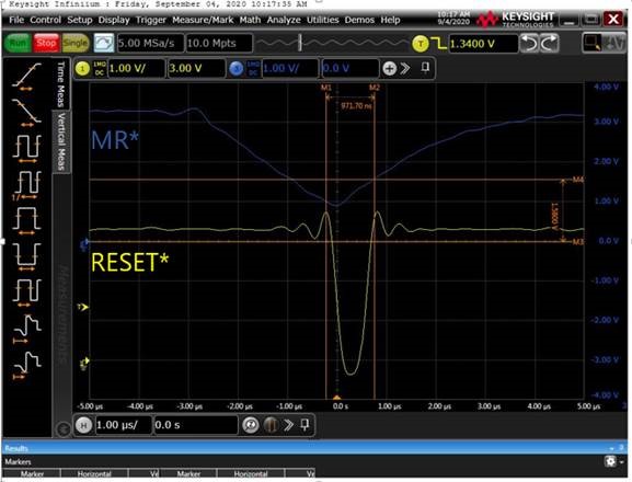
- Signal capture #2 (Reset output and MR* input)
They asserted MR* input but reset output signal was asserted only about 1us, much shorter than the minimum reset time delay of 50 us.
Can you please check the problem and give advice why the reset signal is working properly?
Regards,
Kevin.