Other Parts Discussed in Thread: TPS25982
Hello TI,
I have a board I designed to control two small brushed DC motors which we have been using in service for about a year. The motor control portion is based on a TI part, the DRV8847S, and that part of the circuit has worked flawlessly with no failures. The two channel motor driver has been programmed (via current sense resistors) to limit each channel of motor drive to 800mA, so the driver IC could pull 1.6A in aggregate, which it does do for brief periods during motor startup. The rest of the board is straightforward and basically consists of a microcontroller, a 5V LDO-based supply for it, and some opamp-based filtering.
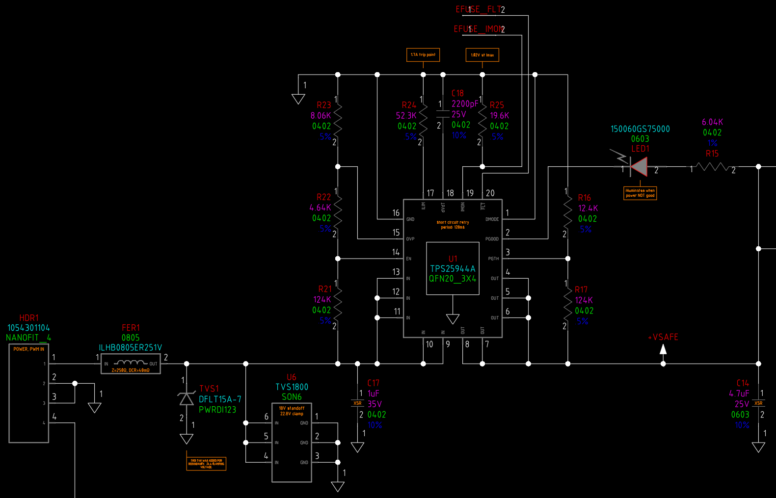
The power input to this board comes from an external, well-regulated 12V switcher. in my design, I implemented a TPS25944A eFuse to provide board-level power protection. I envisioned the eFuse role to be one of secondary protection, given that the motor current is already limited by the DRV8847S. I configured the TPS25944A using the spreadsheet tool provided by TI, and the basic trip level is 1.7A. The circuit is as follows:
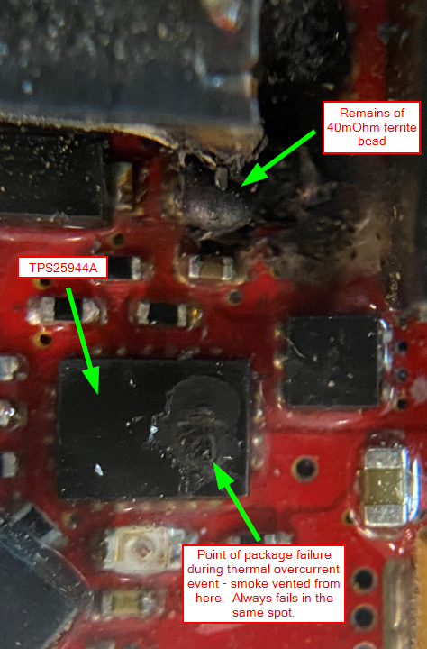
The problem I'm writing about today is that we've experienced a number of destructive failures that seem to suggest there is some kind of serious problem with either the part itself or the way I'm using it. The failure of the TPS25944A is total in the sense that some part of the die (I would assume the pass FET) overheats energetically, violates the integrity of the plastic package, and vents smoke out of a little hole which forms in the top of the package (see pic below). The failure always occurs when the motors are moving; I'm not aware of a case where the TPS25944A dies when it is just sitting powered but idle. There is no hot-plugging involved in our application, and the input voltage to the TPS25994A ramps up gradually and monotonically. I would add that there are two more of these same boards in our system, also with TPS25944A eFuse parts on them, which control different loads (LED lights and a siren, as opposed to motors) and we've never had any failures with them. If there were any input voltage anomaly, it would be seen by all three boards powered from the same bus, and would presumably affect them equally. Some within our company have speculated that some sort of back EMF from the motors is responsible for an over voltage event that is killing the TPS25944A, but that seems unlikely to me given that they are being driven by a purpose-designed part like the DRV8847S that would, by design, allow for recirculating currents through the anti-parallel diodes of the FETs in its H bridges. Also, if there was some excessive voltage impressed on the driver IC and back to the power bus, it seems that it would die first, having an 18V absolute input voltage as opposed to the 20V in tolerance of the TPS25944A. As I noted, we have had zero failures of the motor driver IC.
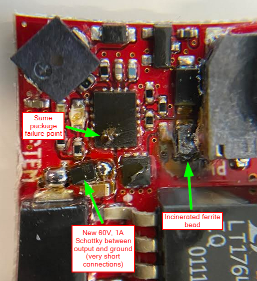
As to the nature of the failure, to me it seems clear that it is a short to ground inside the TPS25944A, as opposed to failing closed, for these reasons: first, if the FET failed closed, I would still see voltage on the output pins, but that isn't the case. Second, when this failure happens, it causes a secondary failure in that a 40mOhm ferrite bead on the input of the TPS25944A (FER1 in the schematic above) passes a very large amount of current and melts down violently. The 12V supply that powers this board is capable of sourcing 10A - more than enough to obliterate the ferrite. There is no visible or measurable fault to ground elsewhere on the board after this failure occurs, so the only location where an amount of current could be sunk sufficient to slag down the ferrite bead is in the eFuse part. Here is a picture which is well representative of the failures we're experiencing:
it I would estimate our failure rate at about 10% thus far (12 failed TPS25944A out of about 100 boards). We are viewing this trend with increasing alarm given that this part is supposed to enhance the safety and reliability of our boards, not degrade it. I have another large project where I already have many more eFuse parts from TI designed in (the TPS25982), but the company mood about TI eFuses right now is not sanguine based on our experience thus far. I would very much like to understand the root cause of these failures, whether it is some limitation flaw in the part itself or an implementation mistake on my part. One possible solution we're about to experiment with is placing a Schottky diode on the output of the TPS25944A in order to address any possible negative voltage; I've already designed this into my new TPS25982 circuits.
My feeling is that as long as absolute part limits are observed (e.g. input voltage), there should be no configuration of passive behavior programming parts that the user could implement that would result in this kind of part failure. I can understand undesirable behavior if the part is misconfigured, but because of the internal thermal shut down protections that engage at 160C, the part should self-protect in all overcurrent situations.
I look forward to whatever help or insight TI can offer. This part is in danger of being designed out unless we can understand the root cause of the failures.