This thread has been locked.

If you have a related question, please click the "Ask a related question" button in the top right corner. The newly created question will be automatically linked to this question.

BQ76952EVM: BQstudio CRC error

Part Number: BQ76952EVM
Other Parts Discussed in Thread: BQ76952, BQSTUDIO

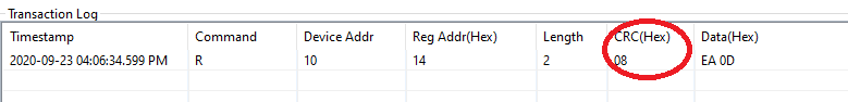
I am using BQ studio to read and write registers of bq76952. Currently communication mode is default i.e. I2C. when i use command sequence tab to send any command read/write it provides a CRC (Hex). how is it calculated as per given document method is generating some thing else.

Do the needful..

  • Hi Dileep,

    Can you send me an example of what you observe? 

    Thanks,

    Matt

  • Hi Matt, 

    I am attaching a screen shot of the command. here in this command parameter for crc are 0x10(Write Add) 0x14(command) 0x11(Read Address) 0xEF(Data LSB) 0x0D (Data MSB ), in this case CRC would be 0x67. But as you can here in the image it is showing 0x03(crc hex).

  • Hi Dileep,

    Your image is not showing up in the post. Can you try to resend the image?

    I do have a couple of CRC examples in the Software Development Guide (see Section 4): https://www.ti.com/lit/an/sluaa11/sluaa11.pdf

    One of the examples shows the same Cell1 Voltage read (command 0x14) that you are trying:

    0x10 0x14 0x11 0x68 0x33 0x0B 0x31. In this sequence 0x33 is the CRC for [0x10 0x14 0x11 0x68] and 0x31 is the CRC for the 2nd byte [0x0B].

    This example uses a repeated start. If your transaction has an I2C stop and then a start, it will change the first CRC calculation (will not include the 0x10 0x14).

    Best regards,

    Matt

  • Hi Matt, 

    I have seen those examples and already gone through that document. But my question is that  in default condition there is no CRC, but still when i am going to use "COMMAND SEQUENCE"  tab of BqStudio it shows a column of CRC but this value not the same what it should be as per examples.

    I am attaching a snap shot please look at this.

  • One more Thing i want to add, sometimes garbages values are also  received. Mostly in the case of CC2.

  • Hi Dileep,

    I see where the confusion is. This CRC displayed in BQStudio on the Command Sequence screen is something different - it is not the actual CRC being returned by the device. I am not entirely sure why this is displayed in the Command Sequence window. I thought you were seeing the strange CRC on the I2C bus.

    I think this value in BQStudio is calculated as the sum of the inverse of the sum of the data bytes. For example NOT(0xEA + 0x0D) = 0x08. 

    By default, the BQ76952 does not have CRC enabled. If you enable it by changing the Comm Type to 0x12 and then click the SWAP_COMM_MODE command and restart BQStudio, the device will then be communicating with BQStudio in CRC mode. When you read the Cell1 voltage with the 0x14 command, the I2C reading will show 2 different CRC bytes as I described in my last reply. The Command Window will not display the CRC from the I2C bus.

    The CC2 reading is updated every 3ms (or every 1.5ms if FASTADC=1). 

    Best regards,

    Matt

  • Hi Matt,

    Could you please give me some example of CRC of Read SubCommand & Write Sub Command

  • Hi Dileep,

    Please see the image below for two examples:

    Best regards,

    Matt

  • Thanks Matt.

     I have gone through the same already that is why i asked for "SUB Command Read/Write". Anyways thanks i have done by myself.