Because of the holidays, TI E2E™ design support forum responses will be delayed from Dec. 25 through Jan. 2. Thank you for your patience.

This thread has been locked.

If you have a related question, please click the "Ask a related question" button in the top right corner. The newly created question will be automatically linked to this question.

TPS63051: Strongly inconstant current with spikes (period 14us) in a 3V3 application (pcb)

Part Number: TPS63051

Dear E2E,

within our team we are using the TPS63051 in a Li-ion battery powered application within a custom miniaturized PCB, which needs 3V3 constant output voltage for powering all the components. I followed all the design suggestions for the choice of the components associated to the regulator (see the image attached).

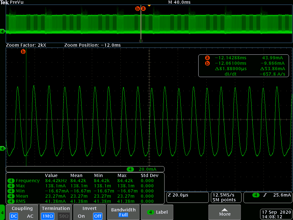
Although, during normal operations, the voltage is constant 3V3 but the current measured from the battery is strongly inconstant, with a mean of 23mA (which is the expected value) but a waveform with continuous oscillations between the values -20 mA to around 100 mA (one hundred) with a period of around 14us. I attached an image from the oscilloscope showing this measurement.

This behavior (oscillations) is not anymore present if we power the device downstream of the regulator, so we suspect that the issue come from there. We also observed that trying to filter the path from the battery to the device with inductors improves the current waveform (becomes more constant).

Do you have any suggestions on the possible cause of this issue and on how to solve it?

Thank you very much in advance.

Best regards,

Gianluca Milani

  • Hi Gianluca:

    What's the load condition during your test? It may enter into PFM

    Please measure the Vin, Vout, L1, L2, and Icoil for debug. Thank you!

  • Dear Minqiu,

    thank you for your support.

    Load condition_ The problem appears both:

    • when the firmware is not present and the only load are the uController and the IMU sensor (in this case we have 3.7V and 13mA from the battery and 3.3V and 15mA(mean) after the regulator)
    • when the firmware is present and also the radio module is active ((in this case we have 3.7V and 24mA(mean) from the battery and 3.3V and 30mA after the regulator)

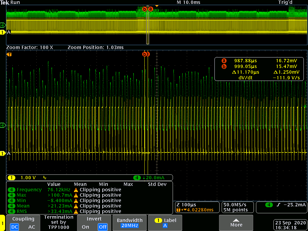
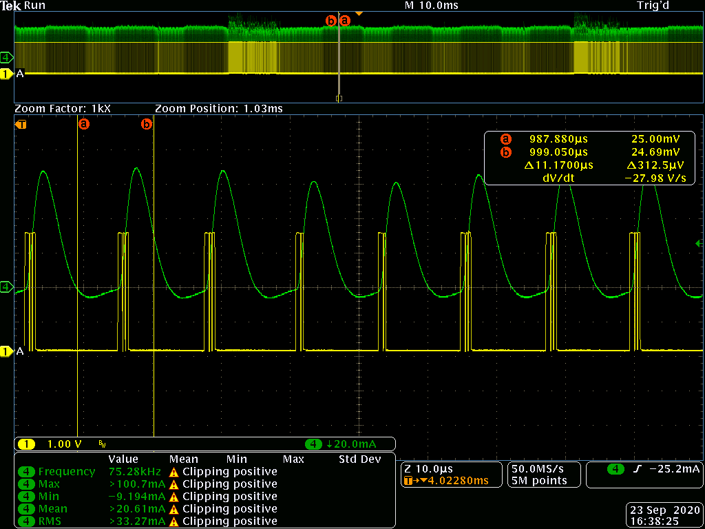
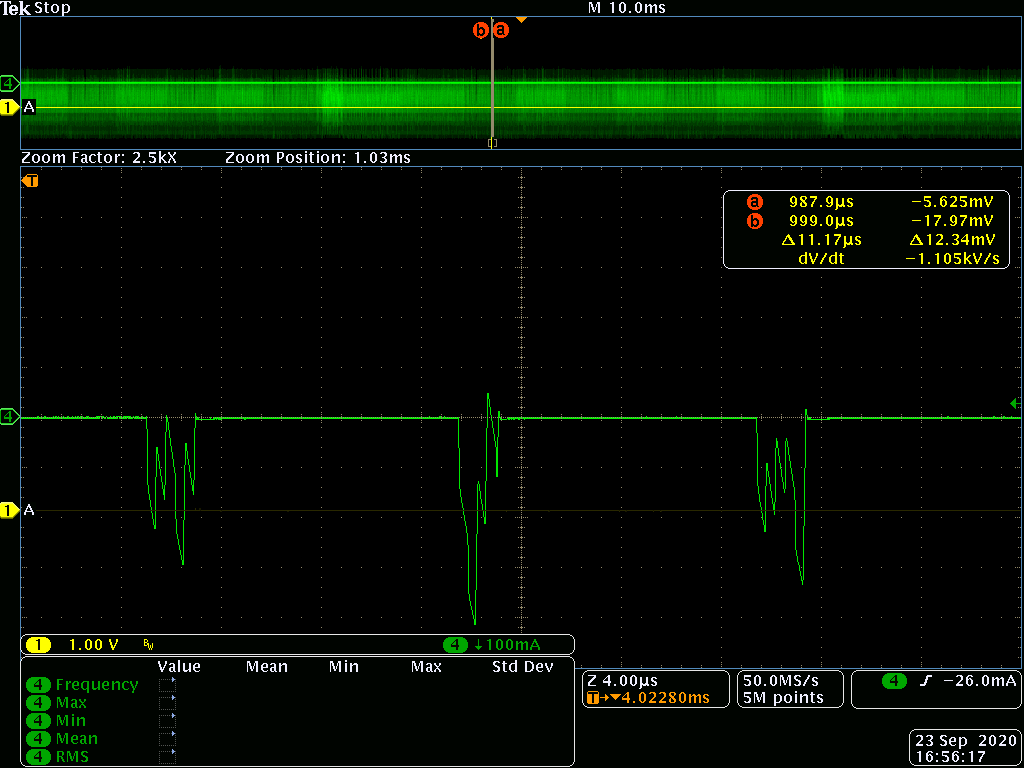
    Here the measurements you asked for:

    Vin=4V constant

    Vout=3.3V constant

    V_L1: in yellow V_L1, in green the current measured from the battery

    V_L2: in yellow V_L2, in green the current measured from the battery

    I_COIL : 

    Let me know,

    Thank you very much in advance,

    Best regards,

    Gianluca Milani

  • Hi Gianluca:

    Sorry that I'm out of office.Please allow me give a simple reply here.

    The issue is caused by power save mode, it looks normal behaviour actually. 

    Will it be harmful for your system? If so, you can disable the power save mode. (you can find the details about Power save model in datasheet.

  • Dear Minqiu,

    Thank you very much for your answer.

    I will try to remove power save mode and to perform some tests, but maybe is ok also power save mode.

    Best regards,

    Gianluca