This thread has been locked.

If you have a related question, please click the "Ask a related question" button in the top right corner. The newly created question will be automatically linked to this question.

LM25119: LM25119 Schematic check

Part Number: LM25119

Hi 

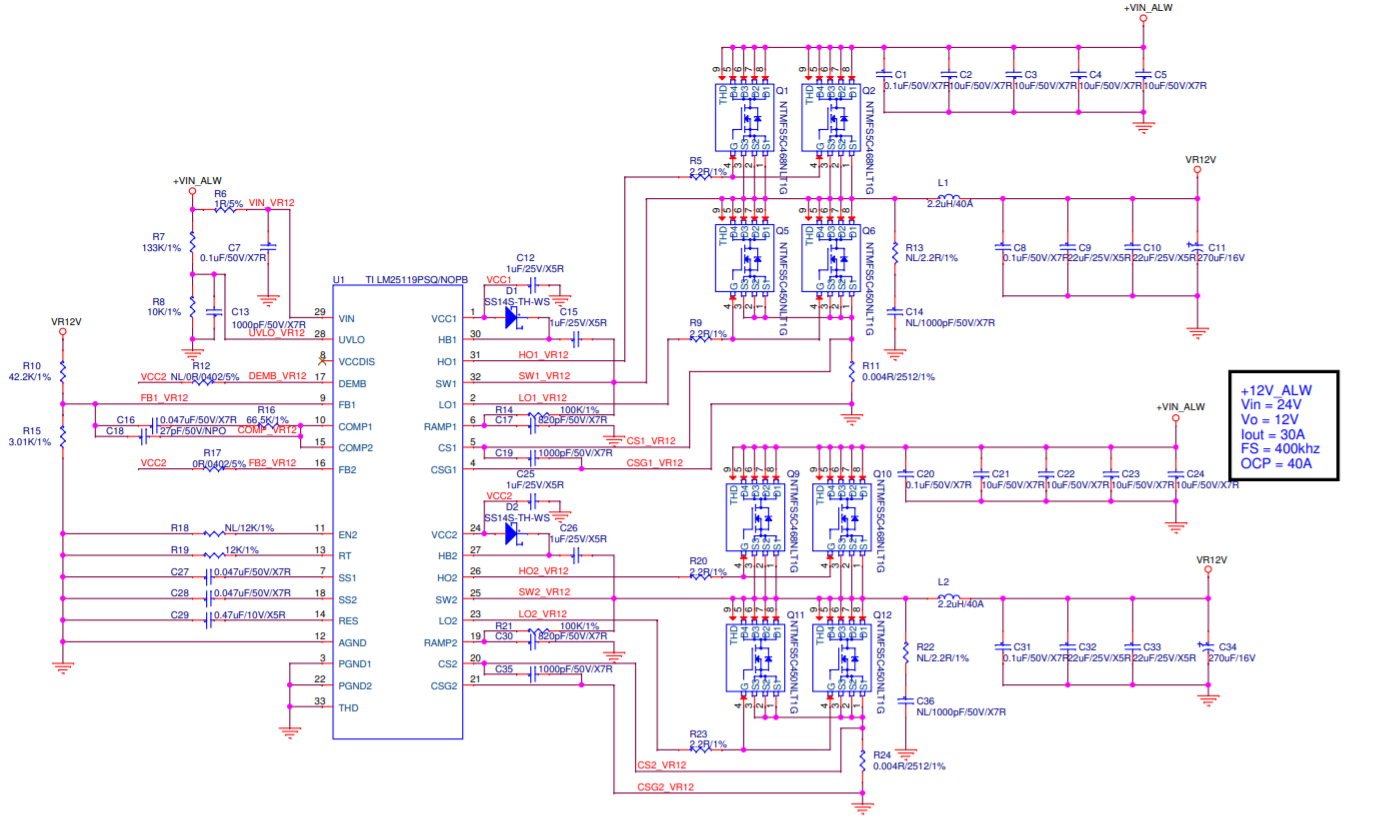
1.Could you help check the LM25119 schematic as below and any need to adjust?

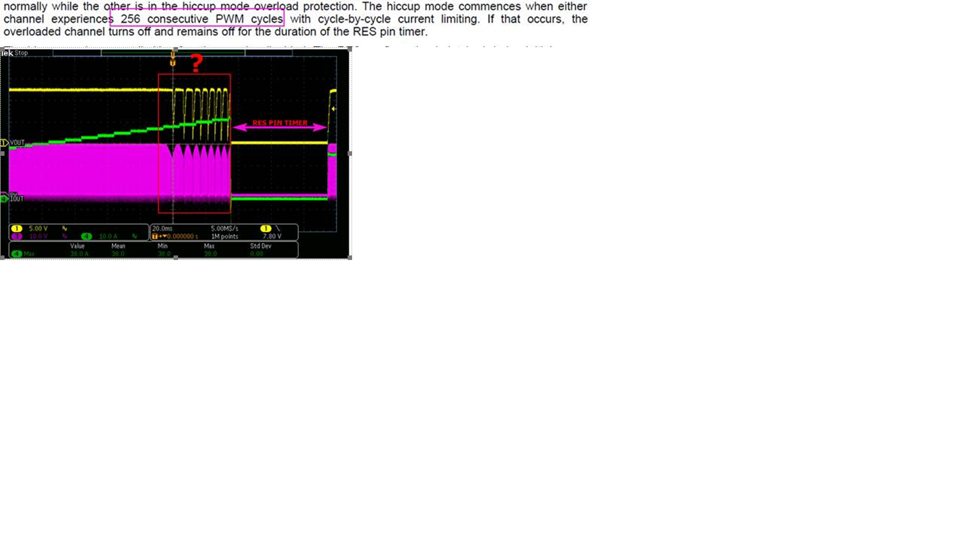
2.When Current limit is in the red box in the figure, Why not just turn it off once and enter the RES pin timer directly?

3.How to calculate 256 consecutive PWM cycles into time, Where to start the calculation?

  • Hi Gareth, I will have an AE review this for you. Please allow a couple of days.  

  • Hi Gareth

     1- For the Schematic review, listed below are my comments on your schametic.

    a - With 100K Ramp resistor and 4 mohm sensing resistance, the Cramp needs to be between 183pF for K =3 to 550 pF for K = 1. With 820pF the K<1 will result in subharmonic oscillations, a K factor closer to 3 will help reduce the Rsense value and the ohmic losses in it.

    Please refer to the LM25119 parameter calculator to estimate these values

    b- R18 connected to EN2 should not be place. EN2 should be floating. If NL in the schematic means that it is not placed then disregard this comment

    c- Add a 10 ohm resistor on the path of CS+ and CS- from the kelvin connection point

    No other comments on the schematic and please follow the layout guideline mentioned in the datasheet

    2- In the Current limit mode the IC is trying keep the current within the desired limits. In some cases the over current condition may be for a short period of time, that's why the IC won't enter the hiccup mode directly to allow some time for the fault condition to go away.

    However, The waveforms are not really showing the current limiting action in the red box. Can you adjust the Ramp capacitor as mentioned in the earlier comment and check back the waveforms. The cycle by cycle current limit will shutdown if the emulated ramp signal exceeds 1.2V.

    3- It is calculated once the cycle by cycle current limit starts when the current exceeds the set OC threshold.

    Let me know if you have any further questions

    Thanks

    Mohamed

  • Hi Mohamed

    Thank you very much for your confirmation

    1- We use LM25119_OC calculation, 40A OCP suggested Cramp is 820P, but there may be subharmonic oscillations
    How should we design?

    2- Where will it happen if subharmonic oscillations?

    LM5119_LM25119_OC calculation (1).xlsx

  • Hi Gareth

    I am using the LM25119 Quick Start calculator in this link with the parameters you mentioned in the schematic and i got the 183pF  - 550pF range.

    Attached is the calculator file with the circuit parametersLM(2)5119 QuickStart ICC Modified_Gareth.xlsx

    This is the link for this calculator

    https://www.ti.com/tool/LM25119-5119QUICK-CALC

    Subharmonic oscillations means you will have an unstable system. you can refer to Table 1 in the device datasheet for all the trade-off for selecting the K-factor

    Thanks

    Mohamed