


Hello,
I'm starting to test a converter using the UCC2895-Q1. I've made the necessary modifications in the hardware so I can increase the input voltage little by little seing the main waveforms and the output evolution.
Obviously, working this way, the softstart is over and the modulator is giving the maximum duty cycle (CH1 is QA, CH2 is QB, CH3 is QC, CH4 is QD and F1 is CH1 - CH3):

Is there a way to limit the maximum duty cycle working this way? I found a similar thread here, but the solution of modifying RT/CT is very limiting.
https://e2e.ti.com/support/power-management/f/196/t/750640?tisearch=e2e-sitesearch&keymatch=ucc2895
Right now I have limited the maximum duty cycle limiting the voltage on the EAP pin through a divider:

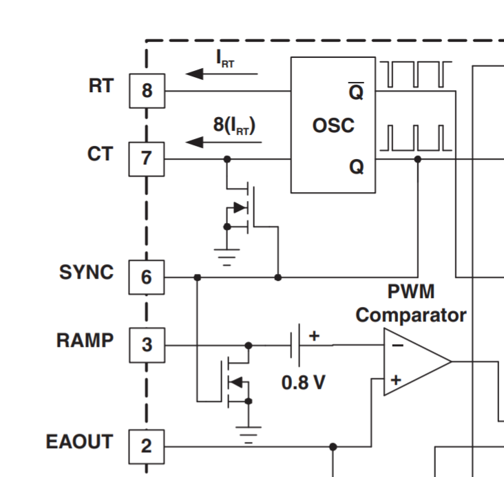
Seeing the block diagram, I expected to be possible to do it through the SYNC input, but if I understand correctly, the block diagram is not correct, as I don't see that a high-level on the SYNC pin induces a low-level on the CT and RAMP pins. I don't understand either the following description of the datasheet: "The internal SYNC circuitry is level-sensitive", as it seems it's edge triggered.
Thank you.
