This thread has been locked.

If you have a related question, please click the "Ask a related question" button in the top right corner. The newly created question will be automatically linked to this question.

TPS23861: TPS23861 VPWR

Part Number: TPS23861

Recently, a problem was found during Poe test. When the tps23861 is connected to some network ports that are not PD devices, the VPWR voltage will be pulled to the ground, resulting in abnormal protection of the back-end power board. After inquiring the network port circuit of this equipment, it is found that the common mode inductor is used to directly ground. But network port equipment manufacturers think their circuits are normal. So is there something wrong with TI's circuit. This makes me wonder. The following is the POE circuit of Ti and the network port equipment circuit, please help to analyze and confirm

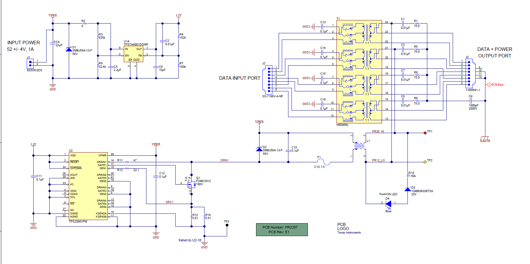
This is ti's recommended circuit

My understanding is from the circuit analysis VPWR circuit voltage is always there, TP1 point is always 48V voltage, TP2 point is through the control of tps23861 and MOS transistor, the voltage control change.

But the circuit of network port is like this

Through the common mode inductance, the VPWR voltage is directly to ground.

  • Hi Kevin,

    The TPS23861EVM circuit have been used many projects in high volumes for many years now. In addition it passes UNH-IOL and SIFOS compliance testing (3rd party PoE compliance testing) without any issues. I don't believe there is an issue with the design. The pass FETs should only turn ON when there is a compliant PD connected. If non-compliant, there should be no power draw and the DCDC powering VPWR should not have to protect itself. You can confirm this by testing this on the EVM with your non PoE load.

    Can you help compare with the EVM to see the differences? I believe there may be something on your application board that can be incorrectly connected.

  • What I want to confirm is whether the LAN circuit diagram of this non PD device is correct. Can you help me confirm it? He put the signal directly to the ground with a common mode inductor? Is this ok?

  • Hi Long,

    Since we focus on the power, I don't see many circuits on the data side of the transformer; however, I will say I have NOT seen this type of connection in the past. Usually I see a protection device in between these lines and not this type of filtering.