This thread has been locked.

If you have a related question, please click the "Ask a related question" button in the top right corner. The newly created question will be automatically linked to this question.

TPS23861:How to right connect supply

Other Parts Discussed in Thread: TLK105L, TPS23861, TPS23881, TPS23882

Hello experts,

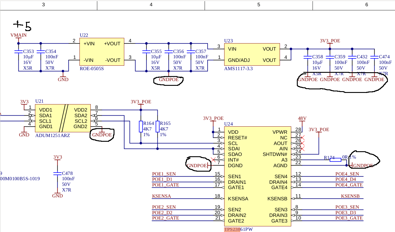
I have a problems on my board. I use TLK105L + TPS23861 but the problem is: When I turn on 48 VDC on my board and connect some device (for example DES-1016A) the TLK105L starts to heat up and after couple of seconds  short (pin12) to the ground =(. I thought the problem with TLK105L and I started this topic:https://e2e.ti.com/support/interface/f/138/p/942332/3482681#3482681  but now I think the problem is much more deeper. When I didn't use PoE and my 48 VDC is power off everything is good. Maybe the problem with supply I am not sure about it. I will give you scheme for for analysis maybe you can help me....

AM574X_INDUSTRIAL_EVM_SCH_PoE_cropped.pdf

AM574X_INDUSTRIAL_EVM_SCH_1_0A_cropped.pdf

Best Regards,

Oleg

  • Hi Oleg,

    What catches my eye on the schematic is:

    1. 3.3V rail must come up AFTER 48V VPWR has reached its UVLO. This is a startup requirement.
    2. R148 and R149 and R151 and R150 should not be installed. To be compliant, it should be 2 pair power.
    3. C523/527/529/533 should be 100V caps

    I'm not sure how this relates to the PHY though as they are on separate ground potentials. The power of the PSE should not really affect the data side since there should be independent of each other. Maybe there is a ground connection somewhere on the board that connecting them together?

  • Also, are you sure the data transformer that was selected can handle PoE? Usually there is a spec that shows DC current capability or the PoE standard that it can be used with (like IEEE802.3.at).

  • Hello Darwin,

    Yes I'am sure transformer is good and compatible with IEEE802.3.at.

    It is information from datasheet...

    1.I am not sure about 3.3 V Rail....As you can see on the diagram in my case, VDD +3.3 is powered from another source. But at the same time, as I see on the diagram from datasheet, AGND and DGND are combined....or they should have different grounds? I am not sure ...Can I use 3.3v from another ac/dc power source or like you sad it should be after 48V.

    2.About resistors R148 and R149 and R151 and R150...it is 0 Ohm and does not matter actually.

    3.About capacitors you are absolutely right they work to their limits.

    I checked the circuit and no found ground connections.....
    BR,
    Oleg

  • Hi Oleg,

    I'm not so sure, IEEE802.3 is the ethernet standard (data) and NOT PoE while IEEE802.3at adds the PoE portion. The datasheet saying IEEE802.3 does not mean it can handle power (otherwise it would say IEEE802.3at or IEEE802.3af or IEEE802.3bt if PoE). Or it would show a current rating which I also did not see in the datasheet.

    1. Yes you can try powering the 3.3V rail with a separate power supply and power it up AFTER 48V. Also, I recommend replacing the TPS23861. If the board was powering up originally with improper sequence, then the IC maybe could not be operating to spec.

  • Hello Darwin,

    I change my transformer on SM51625EL but situation is no changed.

    I can't uderstand why I should supply tps23861 AFTER 48V. In my case I have separated supply 

    through ROE-0505s. You can check it on this scheme, also TPS have different grounds.
  • Hi Oleg,

    The comment about the 3V3_POE was only a schematic comment for the PSE.

    This should NOT affect what is going on the TLK part. I have also looked at the schematic and do NOT see a ground connection that could be relating the PSE and the TLK part. Did you try checking on your board directly if they are connected by ohm-ing it out with a multi meter? Maybe the schematic is correct but something on the board itself is incorrect or maybe a wrong component is populated on the TLK circuit?

  • Hello Darwin,

    I checked my scheme twice  and try to check ground connection with multi meter like you reccomend. But everything is ok....

    I found some strange thing....when I connect my Usb cable for debug console in my pc and try to make couple of measurements between groud pad TLK and pins of ethernet cable which connect to DES1016A I have about 70v. I think the problem in  voltage flowing from capacitors which installed on power supply my pc.

    Any way I will replace TLK and try to not connect usb cable. I mean the reason of problem can be lack of isolation. I will chat you about result maybe you will found somethink too.

    I went to the TLK page and I see that this chip is not recommended for use in new devices, how can you comment on this?
    BR,
    Oleg

  • Hi Oleg,

    I agree, there maybe some isolation issue or some grounding maybe to earth ground that causing this behavior. When the USB is connected, it should be connected to earth ground since the connector is metal. Do you know if SGND on your board connects to earth ground? Or are you using shielded ethernet cable as well?

  • Hello Darwin,

    Like I understood I didn't use shielded ethernet cable and I haven't ground connection on my board.

    If you mean USB cable yes it is shielded like 99% usb cables...but I found interesting thing look at the scheme:

    The tupical scheme Power suply pc have a 2 capacitors (filter) and middle point of this filter is connected to case of pc. We have a 220v Input voltage and I am not sure about ground maybe we haven't normal ground in the socket. like you see grounds is united ....Obviously we will have about 1/2 of imput voltage it is aproximatly 100v on a gnd.

    BR,

    Oleg

  • Hi Oleg,

    Is it possible to modify your board to wire your data portion of your board to the TPS23861EVM? This will help see if it is on the PoE side of your design or not. Thanks!

  • Hello Darwin,

    I didn't quite understand you....what exactly should I modify on the board?

    BR,

    Oleg

  • Hi Oleg,

    Since the EVM showcases the power portion and data transformer, I was thinking you can take the data transformer output on the EVM and connect it to the PHY portion of your board, then remove the power portion on your board. This way you can see if there is a difference between the power portion of your board and the EVM. If there is no issue, then it could be power portion of your board that we can debug. If there still is an issue, then it could be PHY side of your board.

  • Hi Darwin,

    Actually I still misunderstand you but the problem is I no have EVM board only 1 my castom.

    The circuitry for my custom board is similar to the one used on the EVM. With the exception of the transformers which are built into the connector on the EVM and are not shown in the original diagram, in any case, 48 volt power is supplied after the transformer. Thus, the TLK105L is isolated by a transformer. I repeat that there is no such problem with the KSZ9031RN. The problem manifests itself only where TLK105L are installed.

    BR,

    Oleg

  • Hi Oleg, thanks for clarifying. I was originally trying to debug TLK with TPS23861 solution from a PoE prospective since I am the apps engineer for PoE PSE. But if you say another PHY chip operates correctly, then I do NOT believe it is a TPS23861 PoE design issue. My debug comments above was only to really be certain that the PSE hardware design was not the issue (by bypassing it with the EVM which is a known working design).

    My comments on the TLK part are limited since I'm not familiar with the IC. From a PoE prospective, as long as there is isolation from PoE and data, also the data transformer can support power, and the center taps on the data side is configured to the specs of the PHY, the overall design should be okay. 

  • Hello Darwin,

    Any way, you should write your own driver for tps23861 and test it in different sdk versions. This is not correct. For a long time people have been using a third-party driver from git.

    BR,

    Oleg

  • Hi Oleg,

    Thanks for your honest feedback and understand the need for a more complete PSE system solution. For our more recent PSE controllers like TPS23881 and TPS23882, we have made a complete system software solution called FirmPSE that allows support up to 48 ports with port power management and priority, multi-power supply, legacy detection and more.

    I recommend looking at the TPS23882 datasheet since you are currently looking at the TPS23861 which has more information on FirmPSE solution. Thanks!

  • Hi Darwin,

    Do you mean FirmPSE includ support TPS23861 or you reccomend me to migrate on TPS23882 ??

    In my opinion tps23861 is enought for my device with 4 ports... TPS23882 will be redundant and expensive.

    BR,

    Oleg

  • Hi Oleg, that is correct unfortunately. FirmPSE support is only compatible with our newer TPS23881 (4 port 90W) and TPS23882 (8 port 30W) PSE controllers so you would have to switch to these devices since FirmPSE is not compatible with TPS23861 (although we do have TPS23861 reference code available its product page). Yes if your solution is only 4 port requirement, then TPS23882 solution would have 4 unused ports.