This thread has been locked.

If you have a related question, please click the "Ask a related question" button in the top right corner. The newly created question will be automatically linked to this question.

LM74700-Q1: When spec over source current to FET gate

Guru 11170 points
Part Number: LM74700-Q1

Hello E2E,

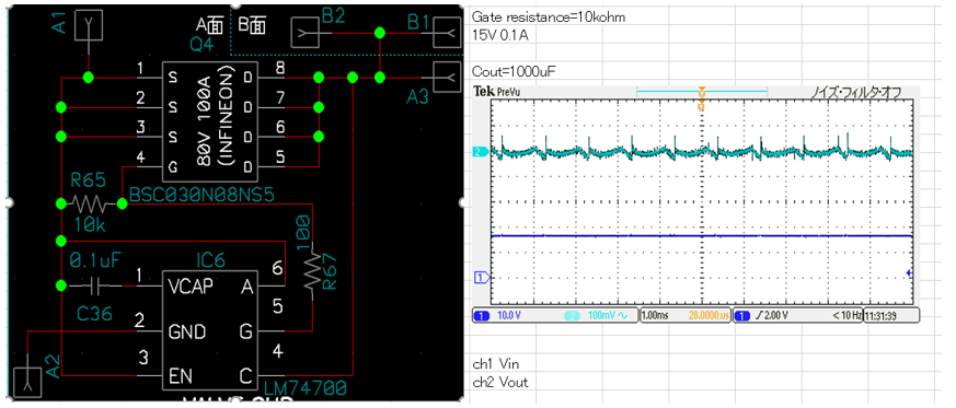
High current FET has large Ciss.
If the source current of the LM74700 over the spec (Igate 11mAtyp), Is LM74700 stop?

Regards,
ACGUY

  • Hi ACGUY,

    The controller will limit Igate to 11mA (typ) which means it takes longer time to charge FET having higher gate capacitance.

    Igate = Qgs/ dt.  => turn-ON time dt = Qgs/11mA.

    For fast turn-on, please consider LM7480Q1 device.

    Best Regards, Rakesh

  • Hello Rakesh,

    Thank you for reply.
    When I using low_Ron FET with LM74700, the LM74700 repeats source and sink on Gate-pin, the output voltage oscillates.
    I inserted resister(18k-ohm ~ 47k-ohm) between to Gate-pin and FET Gate, the output voltage oscillation was suppressed.
    I think it is because the peak current to the FET Gate is suppressed.

    Please let me know your opinion.

    Best regards,
    ACGUY

  • Hi ACGUY,

    What is the load during your test ?

  • Hello Rakesh,

    Vin = 15V

    Iout(max) = 30A

    Using FET : BSC030N08NS5 (Infineon)

    When Iout less than 1A, the output voltage oscillates.

    Best regards,

    ACGUY

  • Hi ACGUY,

    Thanks for the details.

    We should not see oscillations at 1A. What is the Cout ?

    The gate resistor in the order of 18k-ohm ~ 47k-ohm is not recommended as it affects the turn-off response.

    Best Regards, Rakesh

  • Hi Rakesh,

    Cout is 1000uF (470uF * 2). And the circuit board has 10-cm cable on output. Do you have any concern for this composition?

    Regards,

    ACGUY

  • Hi ACGUY,

    Is the load switching? The ripple might be due to a switching load through the cable ?

    Can you share block diagram and schematics.

    Can you share test waveform of load current, Vout, GATE and input voltages.

    Best Regards, Rakesh

  • Hello Rakesh,

    I correct the information. Its resistance is between FET_Gate and FET_Sourse.

    Load current is constant. I attached waveform and schematic. 

    The output voltage oscillates when the load current decreases.

    Regards,

    ACGUY

  • Hi ACGUY,

    Is 0.1A the load current here ? Do you see similar ripple on Vin ?

    Can you please share test waveform in a single scope-shot.

    1. Load current, Vout, GATE and input voltages. include Math function (Vin-Vout)

    Best Regards, Rakesh