This thread has been locked.

If you have a related question, please click the "Ask a related question" button in the top right corner. The newly created question will be automatically linked to this question.

UCC28951: UCC28950 / UCC28951 Burst Mode Setting

Part Number: UCC28951

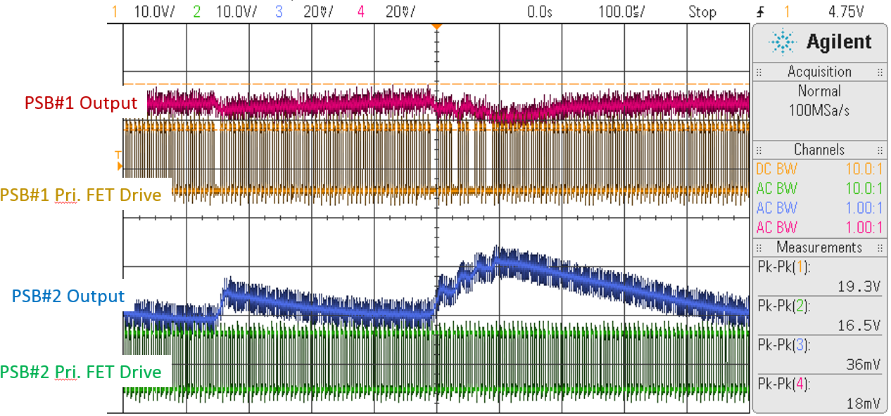
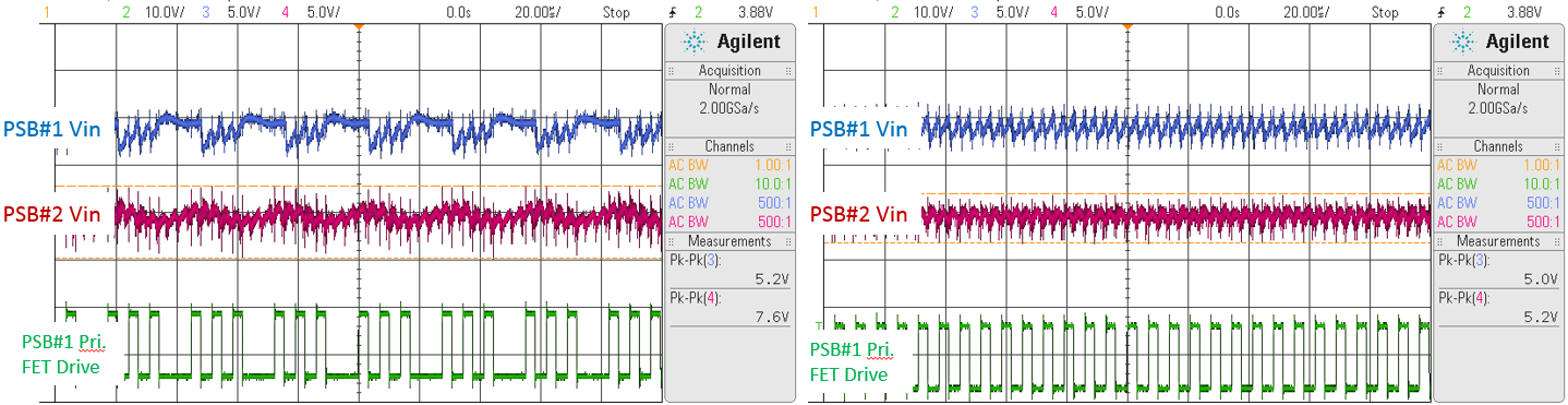
I have a problem with my Phase-Shifted Bridge going into Burst Mode. I have two phase-shifted bridges side by side on the same PCB and connected to the same high voltage bus with LC filters on the front-end of each bridge.  The bridges are synchronized (both in slave mode) and outputting different voltages.  The problem is that when one of the bridges goes into burst mode it induces a disturbance on the other bridges output (see screenshots). I'm not sure if it's the modulation on the high voltage bus that's causing the issue or if it's parasitics. I do know that the problem goes away when the controller exists burst mode.

I'm using the UCC28951 controller and have set Rtmin to 10k (the lowest value allowed by the datasheet). I'm trying to prevent the controller from going into burst mode, but previous forum posts show that there is no way to completely disable it.  Can I set Rtmin to less than 10k? What are the implications of doing this? Is there any other way to prevent burst mode or mitigate its effects to the output voltage ripple?

  • Looks like the images didn't get posted. Trying again:

  • Hi Christopher,

    An expert will get back to you soon !

  • Hi Christopher

    1/ If you are using Synchronous Rectifiers you can disable burst mode by shorting the DCM pin to GND in which case the SRs run continuously. Doing this means the output inductor current is continuous so the duty cycle does not reduce as the load goes to zero and you avoid burst mode. This can be done BUT - you will lose ZVS at some light load - so continuous switching at light load or even zero load will incur switching losses. This is probably going to be ok from a 48V bus but could be a problem at 400V. Worth checking out in any case.

    2/ Cross talk is a fairly common issue with multiple power stages operating in close proximity.

    If it were due to a variation of the DC input bus then I'd expect the output variations to be in phase but in the plot they are in antiphase - Definitely check the DC input bus but I think you will find that variations on one bus don't affect the other. Do you have a possibility to run the two stages from completely separate busses ?

    The two outputs track each other (in anti phase of course) during the bursts but also during the intervals between bursts - This makes me think that there is a common ground connection and the output voltage sensing on the second output is seeing variations due to the currents from the first output. I think these are low frequency effects so I'd suggest you add some heavy tinned copper wire in the ground return path - especially from the output voltage terminals back to the GND pins of the two ICs.

    There could also be some coupling due to capacitive coupling across to the error amplifier (EA-) input but I'd suggest you try adding the copper first.

    Please let us know how you get on.

    Regards

    Colin

  • Hi Christopher

    I neglected to comment on the input voltage variations. These look like a resonance in the input filter. You might like to reduce the amplitude of the resonance increasing the amount of capacitance at the input to the second bridge. There are methods available to dampen the resonances non-dissipatively, but let's see if the input filter is responsible first.

    Regards

    Colin

  • Hi Colin,

    1. Unfortunately I can't put the controller in forced CCM because I'm paralleling the outputs of multiple modules and learned the hard way that doing that can lead to synchronous FET failure. That is why I'm using DCM at light loads to prevent reverse current through my output inductor. Is there any other way to disable burst mode or reduce Rtmin less than 10k or trick the controller into not going into burst mode? I don't care about ZVS at light load.
    2. You are right that the outputs of the bridges share a common ground. I haven't had a chance to experiment with the heavy copper wire in the return path.
    3. I was able to separate the high voltage inputs to each of the bridges and found that the problem persists. This leads me to believe that the problem is EMI related rather than a result of the high voltage input modulation. Perhaps there is a regular noise spike on the CS or EA signal that when omitted by the lack of one bridge switching results in a modulation on the other bridge's output. I will investigate further.

    -Chris

  • Hello Chris

    I'm afraid there is no way to defeat the burst mode. There are some 'tricks' you can try to make entry into burst mode less likely but none of them would guarantee absence of burst mode under all circumstances. Here's an outline - Set Tmin as low as possible. Increasing the shim or leakage inductance increases the time needed to reverse the direction of the current in the primary. This time is sometimes referred to as 'duty cycle loss'. The thing is that this reversal happens after the Ton time has started BUT no energy transfer happens until after the current has reversed. Essentially, this duty cycle loss time subtracts from the effective duty cycle but not from the duty cycle commanded by the controller. Example, set Tmin to 100ns, time needed to reverse the current is 100ns, then the effective duty cycle is 0.  The problem is of course making sure that this process works across variations in components, temperature, switching frequency etc, etc.

    Having said that - I'm sure that we will be able to fix your design so that the interaction that causes the cross-talk is suppressed and the first place I'd look is the ground connections. Ideally there should be no voltage between the GND pin of the controllers and the ground used for output voltage sensing - hence my suggestion for adding copper bars. A longer term solution would be to revise the PCB layout.

    Interesting that the problem persists when you have separate inputs - this eliminates the input as being the source of this problem. Although you may need to go back and review the input filter design to eliminate the resonance (30kHz ?).

    Regards

    Colin