This thread has been locked.

If you have a related question, please click the "Ask a related question" button in the top right corner. The newly created question will be automatically linked to this question.

UCC27710: The high-side driver and low-side driver of UCC27710 could conduct at the same time

Part Number: UCC27710

Hi team,

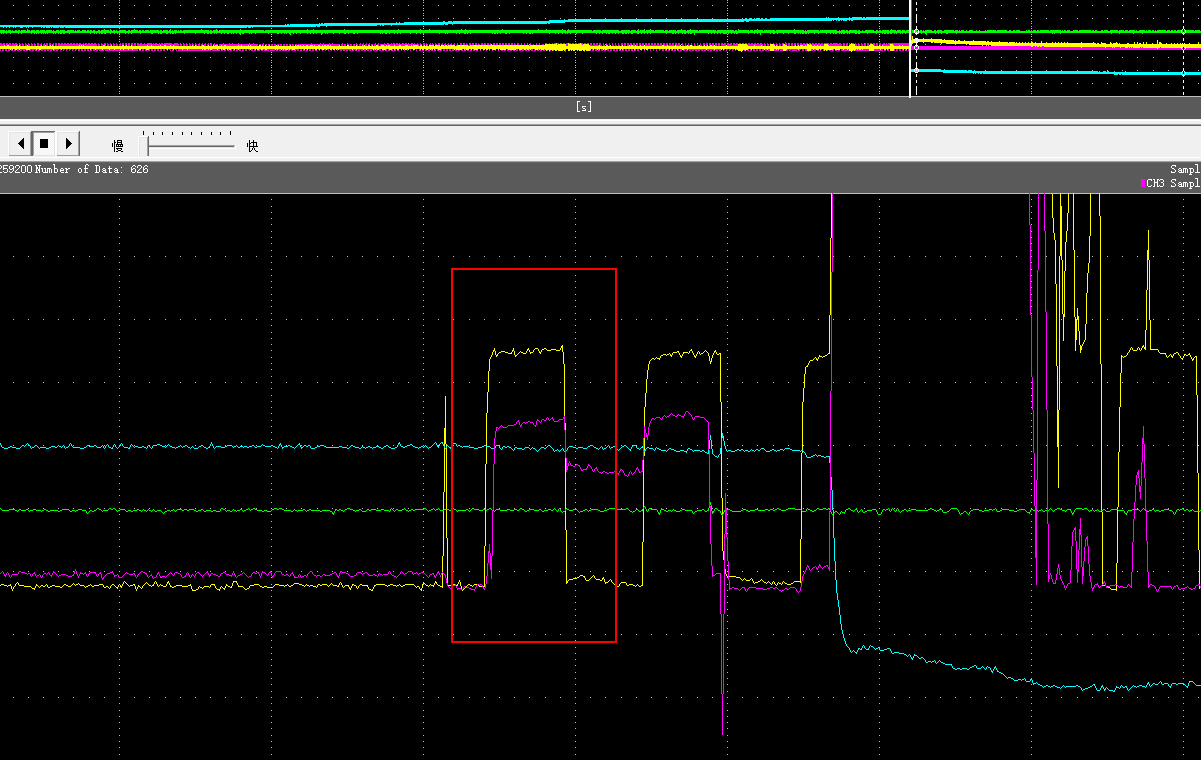
The customer finds a issue that the high-side driver and low-side driver of UCC27710 could conduct at the same time, resulting in broken down. This failure happens and is reproducible it is powered up and powered down for around 100 cycles.

UCC27710 should have inter-lock function to stop this happening. Do you know in what situations that the high-side drive and low-side drive could conduct at the same time?

The waveforms are shown below (Red waveform is HO, Yellow waveform is LO):

X-Ray shows HO failure:

Best regards,

Yang

loop in customer Mr. Luo.

  • Hello Yang & Mr Luo,

    Thanks for reaching out.

    In order to accurately comment on the possible root cause of the issue, if available can you please share the application schematic? If the schematic is proprietary information, you may also share via email where we can follow up.

    On the above plot you shared, what is the blue waveform and what are the voltage scales? 

    Meanwhile I can confirm UCC27710 with the built-in interlock should disable both outputs when the inputs are overlapping therefore in addition to the schematic around the driver, I'd like to confirm the signals below and conditions under which this is occurring specifically and whether the issue is related to driver behavior or the power train effects:

    Capture: HO-HS differential probe, HS to ground, HI to ground, and LI to ground. Second set: HO-ground, HB-ground, HS to ground and HI to ground.

    I ask these waveforms to give me a clue on what the driver IC is seeing from the input side (input signal dead time, etc...) and the signals around the driver IC are within the recommended operating values but also the power train behavior as switch node might not be swinging to GND as expected.

    The failure shown on the x-ray might indicate an issue around the application bootstrap circuit (either not adequately sized for the load, HB-HS exceeding abs max, etc...)

    Regards,

    -Mamadou

  • Hi Mamadou,

    I close the post and we can discuss offline.

    thanks a lot.

    Yang