This thread has been locked.

If you have a related question, please click the "Ask a related question" button in the top right corner. The newly created question will be automatically linked to this question.

LM5170-Q1: LM5170 , 4phase Interchangeable clock with disable circuit breaker function

Part Number: LM5170-Q1
Other Parts Discussed in Thread: LM5170, LM5069

Dear Ti expert:

My circuit is 4phase inter-leave boost converter with disable circuit breaker function.

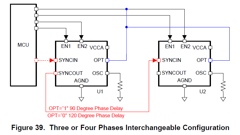
While I follow Fig 39 setting, the LM5170 can't power up due to mosfet failure detection.

How do I fix it with both function (4phase inter-leave and circuit breaker disabled)?

Appreciated you for reply.

Aska

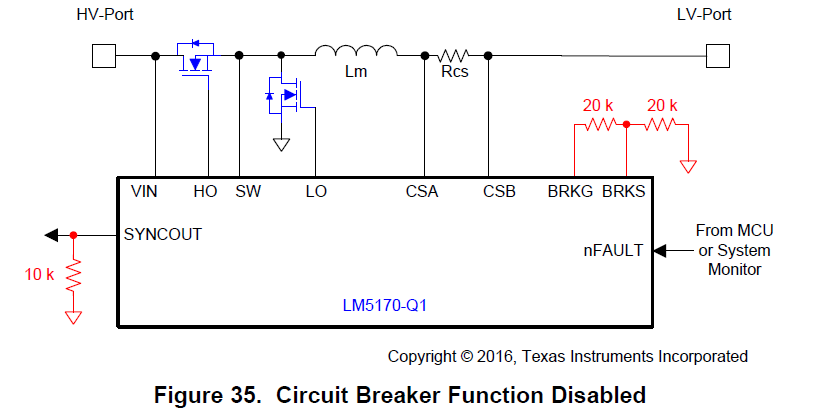
Accroding Fig 35, SYNCOUT shall connect to Gnd through 10k ohm.

Accroding Fig 39, Master SYNCOUT connect to slave SYNCIN

  • Hi Aska,

    Thank you for considering the LM5170 in your design.  You should follow Figure 34 and Figure 39 at the same time to get four phase interleaved operation with Fault detection mode enabled.

    Thanks,

    Youhao Xi, Applications Engineering

  • Dear Youhao:

    It seems the mosfet circuit breaker can't be disable while the circuit is four phase interleaved operation.

    About circuti breaker function, we replace it by exteranl IC (LM5069) for inrush current limit.

    Question 1) The LM5170 circuit breaker can support inrush current limit?

    Question 2) Is it ok for my idea to achieve the 4phase interleaved with circuit breaker disable?

    • SYNCOUT connect to Gnd through 10K for both LM5170 ICs.
    • Provide 2 divided clock (90degree phase lag) to each SYNCIN of LM5170.

    Thanks for your reply.

    Aska

  • Hi Aska,

    The circuit breaker function CAN BE DISABLED in four phase interleave operation.   Each LM5170's SYNCOUT pin should have a 10k resistor to GND.

    Answers to  your two questions:

    1) The LM5170 breaker can support inrush limit. You need to place an RC delay between the BRKG and MOFET gate, but also add a parallel diode to the delay resistor in order to speed up the turn off by BRKG.  

    2). Yes, you can use external circuit breaker controller.  Remember, you need place a 10k resistor across SYNCOUT and GND.  However, you do not have to provide 2 individual clocks.  Use SYNCIN of the 2nd LM5170 to connect SYNCOUT of the 1st LM5170.  

    From these questions I think you concerned about the 10k at SYNCOUT,  that it cannot drive the SYNCIN of the next LM5170 if a 10k to GND is placed at the SYNCOUT.  In fact, the 10k does not affect the clock daisy chain connection.  

    Hope this clarifies.


    Thanks,

    Youhao

  • Dear Youhao:

    Apprecited you help.

    It is very clear for my question.

    I will follow your suggestion and test LM5170 circuit.

    In fact, I power up 4phase LM5170 on my PCB. (The setting is each SYNCOUT of LM5170 connect to Gnd by 10Kohm.)

    Thank you again.

    Happy Moon Festival.

    Aska