This thread has been locked.

If you have a related question, please click the "Ask a related question" button in the top right corner. The newly created question will be automatically linked to this question.

TPS7B86-Q1: Power dissipation graph

Part Number: TPS7B86-Q1

Hello team,

My customer wanted to get some information about Power dissipation as the below picture that is a device of other company.


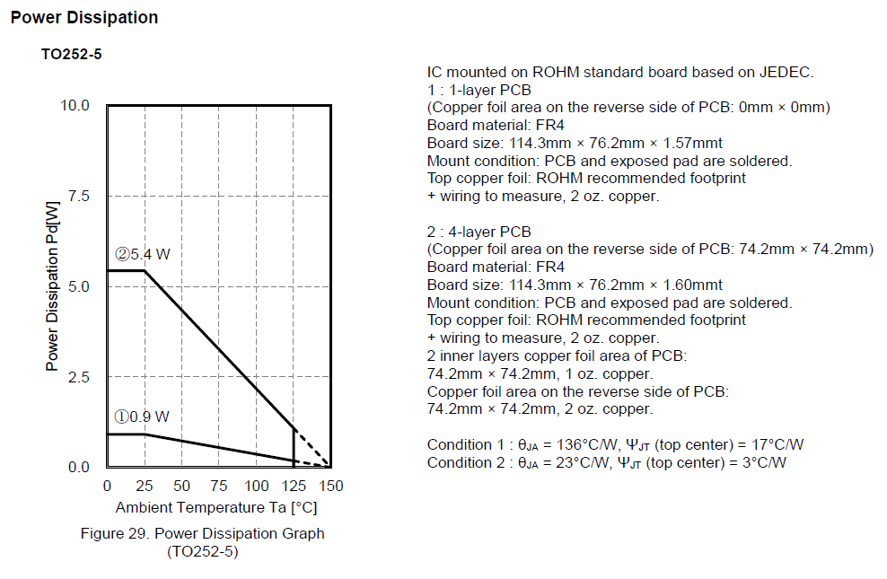
Is there any experimental data about PD of TPS7B86-Q1 not a simple PD calculator?

Thank you.

Best Regards,

Kevin Shin

  • Hello team,

    I added some situation of customer more detail.

    The customer consider TPS7B86-Q1 as voltage drop that is connected to battery. So they concerned thermal issue critically. And if this thermal issue isn't solved perfectly, they think it is difficult to use this device in their board.

    The below is detail spec.

    Vout = 5V, Iout = 230mA, Power consumption = about 2.1W

    Customer wanted to see that this device can operate at 85℃, 2.1W.

    Could you give me some information that the device can operate at that situation? And how much margin for 2.1W of this device?

    Is there any detail information that can verify its feasibility of operation clearly?(ex. Using Ψ parameter)

    Thank you in advance.

    Best Regards,

    Kevin Shin 

  • Hi Kevin,

    We do not have data for the TPS7B86-Q1 specifically, so it may be difficult to exactly quantify this. Here's my analysis:

    I will assume that the customer will use the KVU package since it has the best thermals. For this calculation we can use the R_thetaJA (junction to ambient thermal resistance). At 2.1W, the junction temperature rise is 2.1W * 29.7C/W = 62.37C. With the ambient, the junction temperature would be at 85C + 62.37C = 147.36C. The recommended maximum junction temperature is 150C, so this does not leave a lot of margin. Furthermore, it is difficult to say how much margin is enough on paper because the actual thermal resistance one can achieve is largely dependent on board layout. However, the thermal numbers in the datasheet can be improved upon by laying out the PCB with thermals in mind, as demonstrated in this app note. If the customer is able to use these ideas to thermally optimize their board, the thermal resistances from the datasheet can be reduced quite significantly - enough to provide a comfortable margin - but the level of improvement is on a case-by-case basis. This app note should at least provide a solid reference for them to decide if they are comfortable moving forward with this part if they think they can fit some of these optimizations in.

    I hope this helps. 

    Best regards,

    Nick