


Hi TI Team,
We are using the TPS73501DRVR regulator in our Image sensor's 2.9V analog domain. Attached regulator section for reference (Fig.1). We found lines(noise) in the image sensor output as shown below (Fig.2). We have measured the ripples.
Input = 3.3V
Output=2.9V
2.9V LDO Input (3.3V) ripple = 103mV
2.9V LDO Output ripple =43mV
We have tried the below cases and found the lines in the image sensor.
-
Added 2x10uF cap in C5(input of LDO) -> 3.3V ripple voltage reduced to 60mV from 103mV & 2.9V ripple reduced from 43mV to 28.4mV.
-
Instead of 3.3V input, we provided 5V from Regulated Power Supply -> 2.9V ripple reduced to 21.4mV
-
Added 22uF cap in C6 (output of LDO) So now total 22+1 = 23uF -> 2.9V ripple reduced to 16.6mV
-
Removed R51 and the LDO and sourced 2.9V from the Regulated Power supply. We found no line issue on the camera (Fig.3). The ripple current measured is 15.8mV.
-
We thought that due to the drop out voltage is 400mV (3.3 – 2.9 =0.4) So we increased 3.3V input to 5V. We also get same result. Ripple voltage is 21.4mV and found image line issue.
Please suggest the solution to this issue. What is the problem with this LDO ?
Fig1)
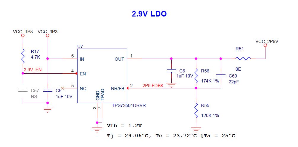
Fig.2)

Fig.3)

Thanks,
Vignesh.M
