This thread has been locked.

If you have a related question, please click the "Ask a related question" button in the top right corner. The newly created question will be automatically linked to this question.

UCC28180: UCC28180: input current distortion

Part Number: UCC28180

Hello,

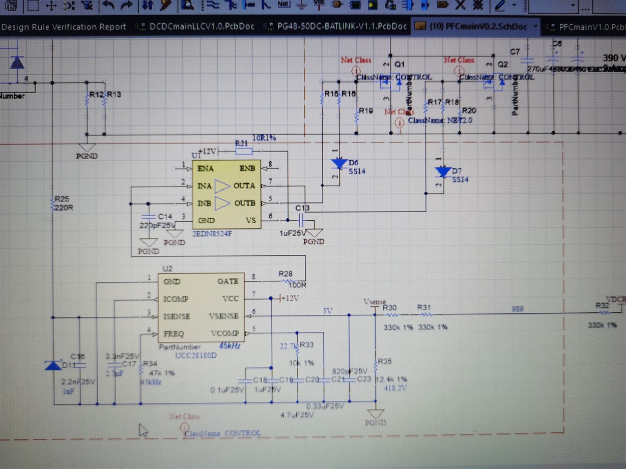
My customer is using UCC28180 for 3KW PFC design. They are confront two problem regarding input current distortion.

Here is the schematic:

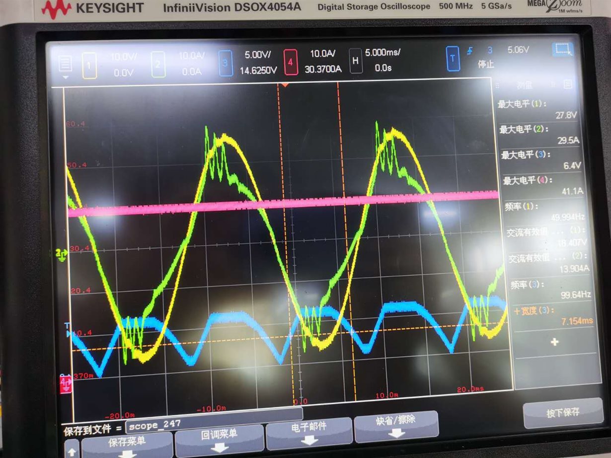
With two 0.01mohm in parallel, they found oscillation on the peak of input current and ICOMP output goes flat, as the following figure:

(Yellow: Input voltage, Green: Input AC current; Blue: ICOMP)

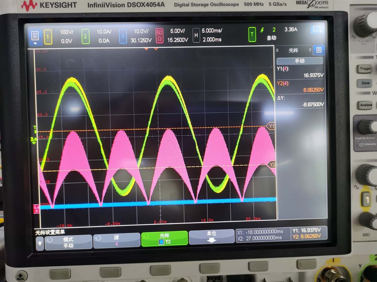
They had tried to decrease the current sense resistor to 3mohm, the current went away as the following figure.

(Yellow: Input voltage, Green: Input AC current; Pink: inductor current)

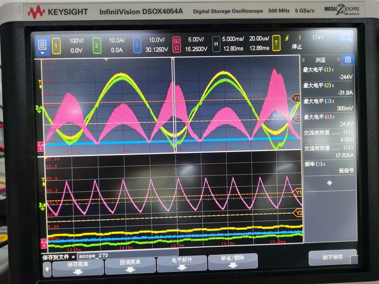
However, with the same condition just when ambient temperature exceeds 45C, one of the current peak goes abnormal. As follow figure.

(Yellow: Input voltage, Green: Input AC current; Pink: inductor current)

They have tried with compensation, but it seems not work.

Could you help analyze above two scenarios and suggest possible cause?

B.R

Paul

  • Hello Paul,

    In the first waveform photo where ICOMP goes flat, the current sense signal was too high ICOMP was driven to its maximum level and the device engaged in peak current limit. Reducing the current sense resistance was the correct solution, as seen in the second waveform photo.

    In the third photo, the inductor current is beginning to saturate. The zoomed current waveform (pink) shows curving slopes which is indicative of soft saturation. This happens at 45C ambient temperature because the higher ambient allows the inductor core to heat up more and this reduces its margin to peak flux density. The boost inductor needs to be redesigned to handle higher peak current at high temperature.  

    The low-frequency current waveform becomes distorted again because the higher inductor current peaks drive ICOMP to its limit again, despite the reduced current sense resistor. The line distortion happens every other half-cycle because VCOMP is reacting to the increased power during the distorted half-cycle and reducing power for the next half-cycle.  But this is over-compensated, so the following half-cycle VCOMP is even higher and the distortion grows.

    VCOMP components can be re-tuned to avoid this, but it doesn't solve the inductor saturation issue. However, redesigning the inductor for higher temp can avoid triggering the peak current limit and avoid the need to change VCOMP values.     

    Regards,
    Ulrich