This thread has been locked.

If you have a related question, please click the "Ask a related question" button in the top right corner. The newly created question will be automatically linked to this question.

UCC28950: UNABLE TO use design tool for spec. SLUC222D (PSFB) ( UCC28950 Excel design Tool),

Part Number: UCC28950
Other Parts Discussed in Thread: TINA-TI, LM5033, UCC28951, UCC28089, PMP8787

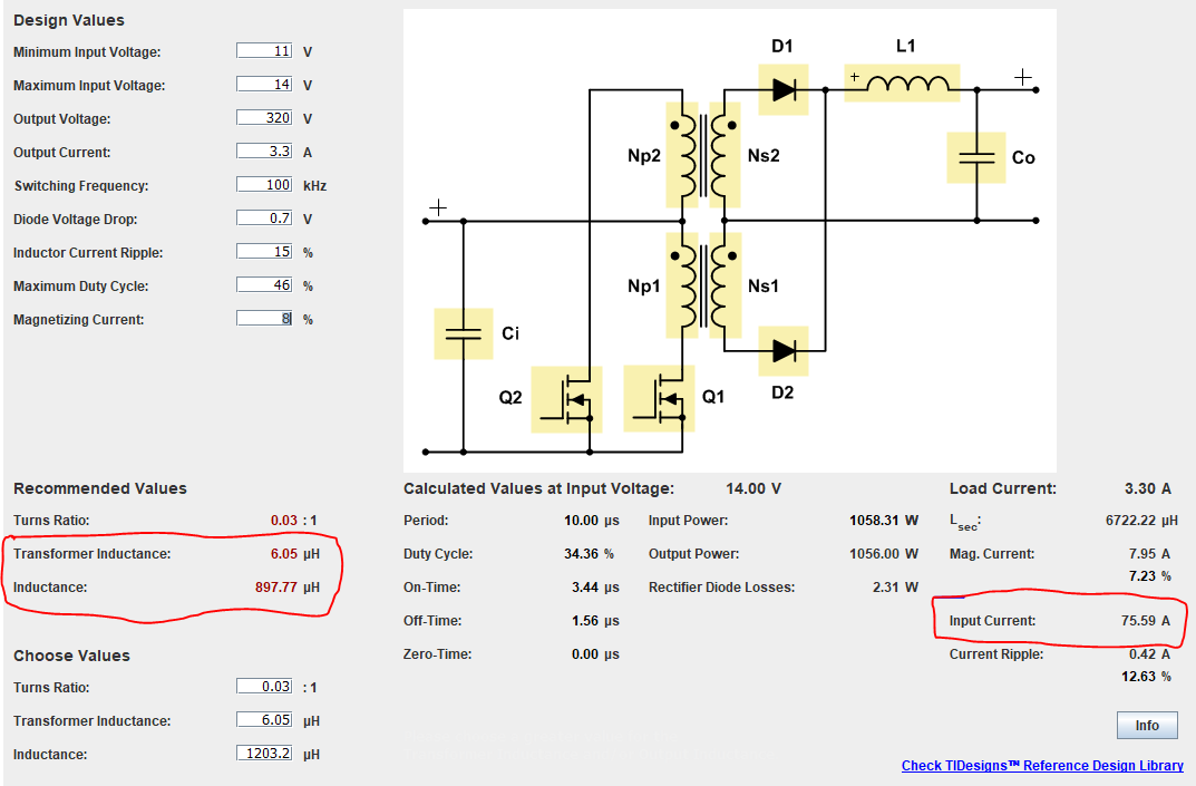
I am trying to use UCC28950 excel design tool for my spec, unfortunately tool shows inductance 0.0H as my application is Step-Up.

input voltage: 12VDC

output : 325VDC

output power : 1KW

Please help with a reference design for the application

Thank you.

  • Hello Rafeeq

    The Phase Shifted Full Bridge is not very well suited to low input voltage applications. The ZVS feature of this topology is important in reducing switching losses at high input voltages but the advantage at low input voltages is not significant. The losses due to the circulating currents that provide the energy to drive the ZVS transitions are higher at lower input voltages too. The PSFB can be made to work at 12V in of course but a push-pull topology is a more usual choice - even at 1kW. I'd suggest that you use a full bridge secondary rectifier too - this will halve the reverse voltage stresses on the rectifiers when compared to a centre tapped secondary.

    The Excel calculator was based on a high input voltage - at lower input voltages it suffers rounding errors so that the required 2.9uH magnetizing inductance is displayed as 0uH. 

    You can run the calculations through the Power Stage Designer tool - you can find it at https://www.ti.com/tool/POWERSTAGE-DESIGNER

    Here's a screenshot of a sample output for your design

    The tool will also calculate a push pull design. Unfortunately the full bridge rectifier is not given as an option - my suggestion is to run a simulation using TINA-TI.

    TI has many push pull controllers - you could look at the LM5033 or UCC2808A devices.

    Regards

    Colin

  • Dear Colin,

    Thank you for your reply with support. kindly share your reply to my query.

    1) you suggest push-pull instead full-bridge , could you brief in short words ?

    2) I tried to simulate same topology (Push-Pull) but i see RED color for most of parameter screenshot attached, could you help ? 

    3) Which PWM controller you receomment for the applicaiton ?

                   a- for Push-Pull

                   b- for H bridge

  • Hello Rafeeq

    1/ I'd recommend the push pull instead of the PSFB because -

    There are no circulating current losses

    Two switches needed on the primary rather than four

    Both switches are ground referenced

    2/ I agree that it's not always clear how to get rid of the red items in Power Stage Designer. Here is a screenshot using your input values - I took the recommended values and inserted them into the fields below the 'Choose Values' text.

    3/ for PSFB I'd recommend the UCC28951.

    for push-pull I'd recommend either the LM5033 or UCC2808A

    Regards

    Colin

  • Dear Colin,

    Thank you for reply, 

    I tried same spec on my pc, unfortunately there is difference in current (marked RED color) on my screen ?

    Could you please clarify ,  i attached screenshot.

    1) what is  "Transformer inductance" & "Inductance" marked RED color 

    2)  can you help on getting reference design of LM5033 or UCC2808A  ?

  • Hello Rafeeq

    The reason for the differences between your results and mine is that they were calculated at different input voltages (11V and 14V). You can look at the waveforms at any of the points highlighted in yellow (Q2 in example below) and then use the cursors to change the input voltage and load current.

    I didn't find any reference designs for the LM5033 but there is an evaluation board available (it's linked on the product page) - you can look at the user guide at https://www.ti.com/lit/ug/snva091a/snva091a.pdf?ts=1601373904806&ref_url=https%253A%252F%252Fwww.ti.com%252Fproduct%252FLM5033

    Unfortunately we don't have a reference design using the UCC2808A either - there are some push pull reference designs in the library https://www.ti.com/sitesearch/docs/universalsearch.tsp?searchTerm=push%20pull%20reference#q=push%20pull%20reference&t=everything&linkId=1 .

    but these are lower power.

    Regards

    Colin

  • Dear Colin,

    thank you for reply,

    1) what is  "Transformer inductance" & "Inductance" marked RED color  (my earlier screenshot) ?

    2) Can you give  a quick comparison about UCC2808A  & LM5033 which is more suitable for me ?

           I have gone through its datasheet but could not take decision which to use.

    3) I understand I can scaleup the power capacity of reference design appropriately changing MOSFET and Xer and other power components, is it right ?

  • Hi Rafeeq

    Oops - I neglected to answer that part of your post -  Transformer inductance is the magnetizing inductance of the primary winding of the transformer. It's not very clear but the term "Inductance" is the inductance of the output inductor.

    Controllers :  The UCC28089 is a push pull controller with low UVLO limits so you would be able to use the input voltage to your system to power it - that's convenient. https://www.ti.com/lit/ds/symlink/ucc28089.pdf?ts=1601376809071&ref_url=https%253A%252F%252Fwww.ti.com%252Fpower-management%252Foffline-isolated-dcdc-controllers-converters%252Fpwm-resonant-controllers%252Fproducts.html

    The UCC2808A is current mode control - which makes loop compensation easier but its min input voltage is 13V so you would have to build a small boost supply to generate its UVLO - our reference design PMP8787 would solve that problem - https://www.ti.com/tool/PMP8787

    The LM5033 has a UVLO at 15V - again the PMP8787 would give it a supply rail but it's voltage mode control only.

    Overall - I think the UCC28089 would be a good choice - unfortunately there is not a reference design for this part. NOT: the typical application schematic shows a low voltage secondary using SRs and a SR controller - that won't be suitable for a high voltage output like you are designing - you should use diode rectification instead.

    Regards

    Colin

  • Dear Colin,

    Let me clarify two points before decision.

    1) I am running on 12V battery (its primary side power source) so PWM controller will directly powerup from 12V input battery.

    2) is LM5033 does not have current mode control ?  as i prefer current mode control its one important selection factor.

    3) I understand SR not good idea for high voltage application. I plan for High voltage FR diode bridge for testing.

    How you recommend to start with UCC28089 design ? as no reference design available but LM5033 already reference design available. 


  • Hello Rafeeq

    If you want the PWM controller to run directly off a 12V battery then the UCC28089 is the better choice.

    I would use the typical application guide schematic on the device data sheet for the primary - the secondary is a bridge rectifier with the Lout and Cout values given by power stage designer. The feedback will have to be isolated unless you have the secondary and primary grounds connected electrically.

    The isolation is normally through an opto-coupler.

    Control of a Voltage Mode Controlled stage is not quite as easy as for a Current Mode Controlled stage but there is a lot of information available - for example at https://www.ti.com/seclit/ml/slup340/slup340.pdf  Voltage mode control will require a Type 3 compensator. 

    I wasn't able to find a current mode controller with the UVLO needed to run off a battery but there is a selection guide at this link

    https://www.ti.com/power-management/offline-isolated-dcdc-controllers-converters/pwm-resonant-controllers/products.html#p1131=Current;Peak%20Current%20Mode&p106min=8.5;11.5

    Feel free to post a sketch of your circuit and I can review it for you.

    Regards

    Colin