This thread has been locked.

If you have a related question, please click the "Ask a related question" button in the top right corner. The newly created question will be automatically linked to this question.

TPS2373: TPS2373; UCC2897

Part Number: TPS2373

Dear TI support,

We do have 2 questions related to the TPS2373.

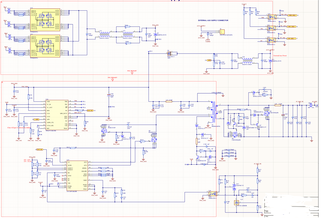
Our application uses the schematic shown below.

1. We found out that the output voltage of the converter is dependant and not stable when you change the AUX input voltage. For example, 54V input generates 8.4V output and 48V input generates 7.8V output. Is this something expected or if not What we need to cure it

2. We found out that when we use AUX power supply, the conducted emission common-mode noise becomes very high (above the CISPR32 limits, starting from ~200kHz. Please see the attached noise report). We are forced to use special common mode chokes in order to suppress the conducted noise. When we operate with PoE the noise becomes very low (almost zero). Dear support please take a look at the schematic and let us know if we can do something to cure the conducted disturbance.

We stay at your disposal if further details are required.

BR

Andrey Marinov

  • Hello,

    Can you show where APD is connected to?

    If this post answers your question, please indicate so by marking this thread as resolved. Thank you.


    Regards, 


    Michael P.

    Applications Engineer

    Texas Instruments 

  • Dear Michael

    By error the previously attached schematic was not complete. Please find the updated image.

    We are looking forward to your reply

  • Thank you very much for the schematic. 

    The change in voltage from the APD input is not expected for a DCDC converter. It could be unstable. What is the phase and gain margins for the design? 

    Also, does the output voltage vary if different voltages are applied on the PoE input?

    As for your second question, it is very common that an EMI choke is needed for both the adapter and the PoE inputs. We do that on our EVM's. I notice the PoE in this schematic has two EMI chokes - this is probably why the EMI is so low comparatively. 

    If this post answers your question, please indicate so by marking this thread as resolved. Thank you.


    Regards, 


    Michael P.

    Applications Engineer

    Texas Instruments 

  • Dear Michael,

    Thank you very much for your reply. I do appreciate your time and effort.

    About question 1.

    In the datasheet p4 is stated that APD is "Auxiliary power detect input. Raise 1.65 V above RTN to disable pass MOSFET, to force TPH active (low) and to force TPL and /BT inactive (open). If not used, connect APD to RTN." I do understand, the voltage level in this case should be above the threshold. Can you please give us some more details behind your statement.

     -> Also, does the output voltage vary if different voltages are applied on the PoE input? We are not able to perform this test due to fixed power injector hardware. Thus we are not able to vary the PoE input voltage. All the tests we do are by vary the AUX supply.

    About question 2

    We develop our converter stage based on the design from the TPS2373-4EVM-758 Evaluation Module.

    Dear Michael, Can we ask you for any source of information (application notes) regarding the phase gain margin for this DCDC converter eval board. I would like to ask you as well about the impedance curve of L11 (250uH) from page 5 of the TPS2373-4EVM-758 datasheet.

    In our design we are forced to use two CMC in series ( as L11) with impedance about ~10kOhms at 1 MHz each in order to reduce the 200kHz noise.

    Thank you for your reply

    BR

    Andrey Marinov

  • Hello,

    1. I was answering your original question: "1. We found out that the output voltage of the converter is dependant and not stable when you change the AUX input voltage. For example, 54V input generates 8.4V output and 48V input generates 7.8V output. Is this something expected or if not What we need to cure it"

    - no this is not expected.

    You can apply 48V across VDD_VSS on the input TVS diode D5. 

    2. The following public paper is useful:  

    Additionally the following paper has some information on the end. 

    This last paper is on Current Control Mode Theory:


    I am not sure what question you have on the impedance curve of an inductor, but it is very likely that your best source of information is the part manufacturer. 

    An important factor in both stability and the load regulation is the transformer. i noticed this part is changed from the design. I would reconsider this part.


    If this post answers your question, please indicate so by marking this thread as resolved. Thank you.


    Regards, 


    Michael P.

    Applications Engineer

    Texas Instruments