Other Parts Discussed in Thread: LM2663
Hi team,
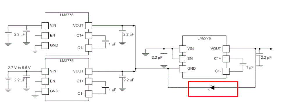
our customer is now using LM2776 to achieve +5.5V to -11V. Below is their block:
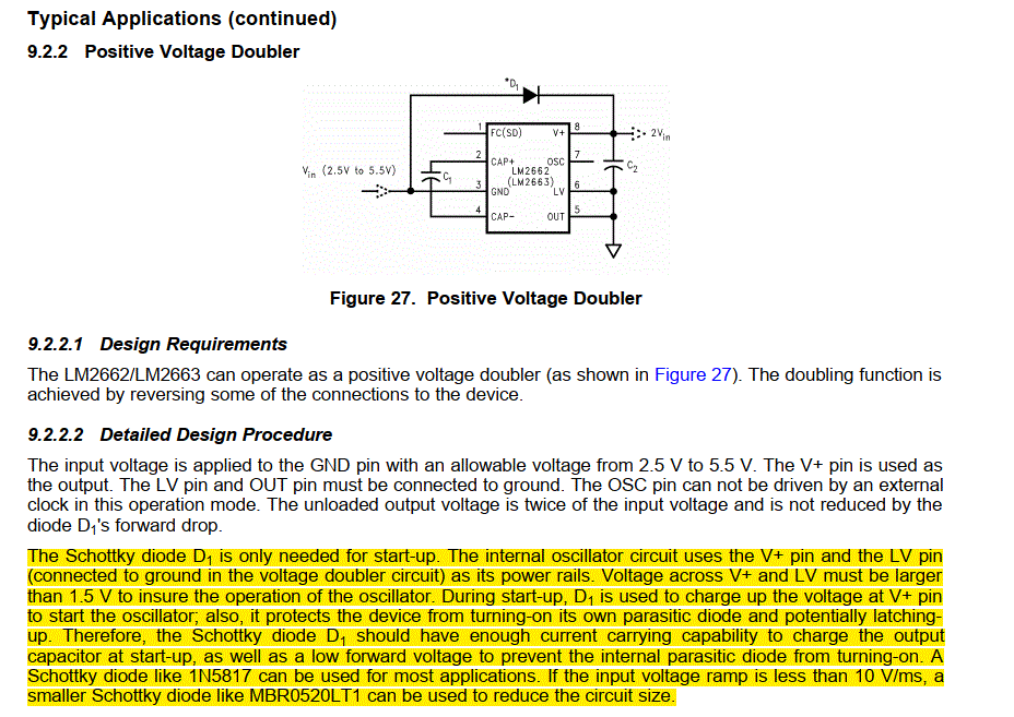
for the diode in the red, they found the following description in the LM2663 manual, but not the LM2776 manual. The rough meaning is to prevent the Vout voltage from being too much higher than GND due to the capacitive load during power-on and start-up, resulting in the internal latching up of the chip and insufficient LV voltage to cause the internal crystal oscillator to fail to oscillate.
The function of the diode on the second stage LM2776 in the above figure is similar to the description of 2663 in their understanding. If they remove the diode in the above figure, it is easy to reproduce the second stage not working when the capacitive load is relatively large or there is a load DC current. Please confirm the following questions.
1.Is there a similar latch protection circuit inside LM2776? Does TI have a design threshold? For example, the voltage of Vout cannot be higher than GND. If the voltage is higher than this threshold, latch-up will occur.
2.The recommended diode for 2663 is 1N5817, is there a corresponding recommendation for 2776? Another situation is that our different projects have different capacitive loads. If the recommended diode is used, what is the maximum capacitive load that can be supported? Have you considered the changes in diode forward voltage at high and low temperatures?
3.Whether the EN pin also has the problem of insufficient voltage when the LV pin similar to 2663 is powered on and the internal crystal oscillator cannot oscillate.


