Dear Sir/Madam,
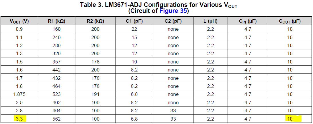
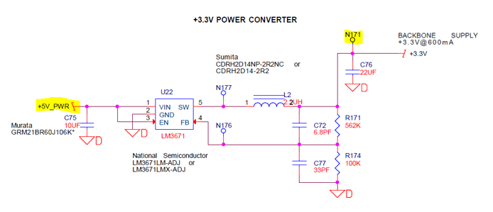
We have performance issue with TI Step-Down DC-DC Converter, LM3671MF-ADJ used in the end products. This part is used to convert 5V supply to 3.3V supplies which provide the power to the processor and supporting memory (flash and SRAM), with typical load of 230mA. Implementation is same in all three parts and used the same Inductor (2.2uH, 1.5A), output capacitor (22uF, X7R, 25V), input capacitor (10uF, X5R, 16V), and feedback loop components.
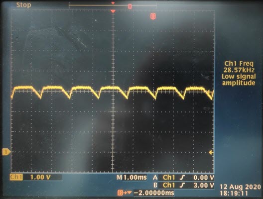
Failure observed is CPU no boot condition, which is attributed to noise / ripple on the 3.3V supply / node. This behavior of the circuit in fault condition is LM3671 stuck in the hick up or low power mode, even current demand is 230mA, thus resulting in ripple / noise on the 3.3V line.
- In some instances, momentarily addition of 100 Ohm load will get the LM3671 out of hick up or low power mode and 3.3V power supply becomes ripple free and CPU boots up normally.
- In other instance, we need to add as large load as 5 Ohm and keep it in circuit, to take the LM3671 out of the hick up or low power mode to make the 3.3V power supply ripple free and CPU to boot.
- In most cases, replacement of LM3671 part in PCBAs, same circuit produces 3.3V power supply ripple free and CPU boot with no issue.
TI has noted layout is not per recommendation and output capacitor is too far from the inductor. To determine the impact of layout.
- A new PCB has rebuilt with this fixed by moving the output capacitor next to inductor and 50% of the reworked PCBAs came out of the hick up or low power mode and 50% of the reworked PCBA remains in the same state of hick up or low power mode .
- End customer has performed additional experiment by adding 1mS from the input power pin 1 to the converter enable pin 3, which made 50% of the remaining 50% of reworked PCBA that did not come out of hick up or low power mode, to come out of the hick up or low power mode. End customer is concerned if TI can help to find out the root caused to fix this known symptomatic issue and to get 100% passed.
Below are the concerns and questions about the behavior of the device and circuit, Need TI to help to explain:
- Why upon replacement of LM3671 make the design perform as expected, with LM3671 that delivered with same specifications?
- Why upon addition of extra resistive load make the output from the LM3671 ripple free?
- Why the value of the extra resistive load required varied from 100 Ohm to 5 Ohm to make the output from the LM3671 to be ripple free from one device to another?
- If the hick up or hi ripple is indication of device in PFM mode, then Why it is stuck in the that mode when current drawn by CPU is typically more than 200mA , which is well above the required value listed in the datasheet of LM3671 to switch into PWM mode?
- If this is the known behavior of the device, then what would TI recommend replacing this device with to avoid above listed issue or issues?
- What are the possible scenarios that can impact the PFM to PWM transition point as noted?
Schematic and test board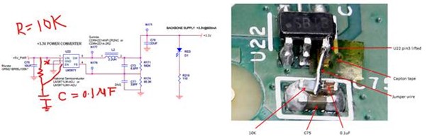
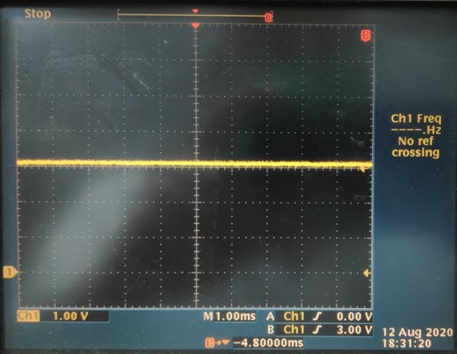
Good part waveform:
Bad part Waveform: