This thread has been locked.

If you have a related question, please click the "Ask a related question" button in the top right corner. The newly created question will be automatically linked to this question.

TPS92682-Q1: Flickering of the LED on PWM ramp up

Part Number: TPS92682-Q1

Hi everyone!

Can you please help me with my problem on ramp up PWM?

After initialization the TPS92682-Q1 in CV-Mode and will ramp up the PWM duty cycle from 0% to x%, the LED will be flickering in the first. If we go back to 0% and start again to increase the duty cycle, there is no problem. 

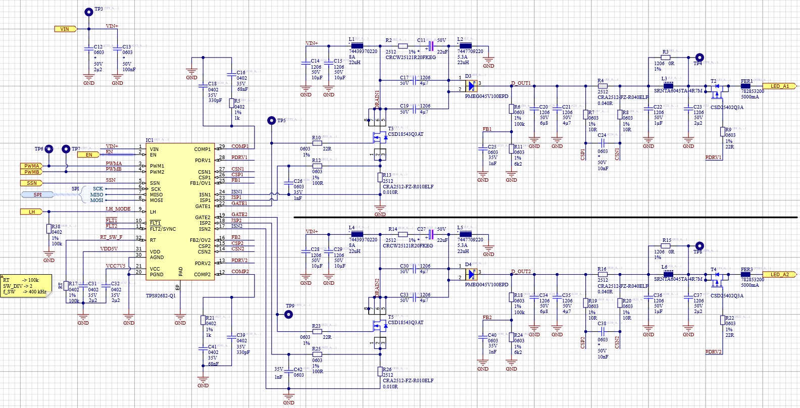
The curcuit is a SEPIC converter similar the TI Reference desing TID-050029 45-W, 15-W dual SEPIC LED driver reference design for automotive lighting. 

We use it in CC and CV Mode and have an Output for max. 4A or 16V.


Thanks Andreas!

  • HI Andreas,

    The PWM duty cycle you are talking about is it the GATE signal or the PWM input signal to the TPS92682.  You are using CV mode to drive and PWM current to the LED's or is there a CC mode controller after the CV mode to drive the current.  

    Thanks Tuan

  • Hi Tuan,

    Thanks for your answer. We are using an externel PWM Driver on PWM Input on the TPS92682. There is in CV and we drive LEDs with series resistors. This is one of our use cases.

    The mode depends on the load device.

    BR

    Andreas

  • Hi Andreas,

    Without knowing all the register settings and your schematic along with operating condition it's hard for me to comment.  If my understanding is correct, when first start up you increase the PWM Dimming input from 0% to 100% duty cycle slowly to the TPS92682 you would get a flicker and then the second ramping of PWM input from 0% to 100% and after you do not get any flickering.  Is that correct?  If it is then my first guess is for you to increase the Soft-Start time in register 06 to max as a test.

    If not then please have the register setting send to me along with schematic and operating conditions.  Please also include scope captures and more description on what you are seeing.

    Thanks Tuan

  • Hi Tuan,

    yes your understanding is correct. The Soft-Start time was also our first thought, but there was no improvement. 

    Below you will find our schematic from the TPS92682 as in SEPIC topic. 

    At the initialization we will set the register:

        // BASIC Init
        TPS92682_Write(spiChannel, RESET, 0xC3);
        TPS92682_Write(spiChannel, ENABLE, 0xB0);
        TPS92682_Read(spiChannel, FLT1);
        TPS92682_Read(spiChannel, FLT2);
        TPS92682_Write(spiChannel, CFG1, 0x01);
        TPS92682_Write(spiChannel, OV, 0b01010101); // ChxOV: 1,125 (threashold 12.5%)
        TPS92682_Write(spiChannel, SOFTSTART, 0b11011101); // SSDIV factor: 64
        TPS92682_Write(spiChannel, FM, 0b00110100); // FMMAG: 15% / FMFREQ: 1 / 2048
        TPS92682_Write(spiChannel, FEN1, 0b00111100); // UV: disabled / RFEN: disabled
        TPS92682_Write(spiChannel, FLATEN, 0x00); // all disabled
        TPS92682_Write(spiChannel, ISLOPE, 0b00010001); // 50mV Slope
        TPS92682_Write(spiChannel, SWDIV, 0x00); // DIV: 2
        TPS92682_Write(spiChannel, ILIM, 0b10100000); // 16 Err till trig /  CHxILIM: 75mV

    For Testing with an LED and series resistor, we change to following:

    CV-Mode, CH1ADJ-Register to 0x3E (10V),

    We increase the PWM via a ramp or external slider from 0% to 100% Duty Cycle. 

    The LED ramp up a little bit and then goes out. When we start again, it will works. 

    Thanks Andreas

  • Hi Andreas,

    Please give me a few days to review this and I will get back to you.

    Thanks Tuan

  • HI Andreas,

    The schematic you have is set up for Constant Current (CC) mode not Constant Voltage mode (CV).  Please see data sheet or the evaluation board below for the design of CV mode. 

    https://www.ti.com/lit/ug/sluubx9a/sluubx9a.pdf?ts=1602272712805&ref_url=https%253A%252F%252Fwww.ti.com%252Ftool%252FTPS92682EVM-069%253FkeyMatch%253DTPS92682%2526tisearch%253DSearch-EN-everything%2526usecase%253DGPN

    You cannot use a CC mode in CV mode since the feedback is different.  If you intend to drive a current to the LED then it's best to use it in CC mode.

    Thanks Tuan