This thread has been locked.

If you have a related question, please click the "Ask a related question" button in the top right corner. The newly created question will be automatically linked to this question.

LM5170EVM-BIDIR: Buck mode doesn't work

Part Number: LM5170EVM-BIDIR
Other Parts Discussed in Thread: LM5170

Hello TI experts,

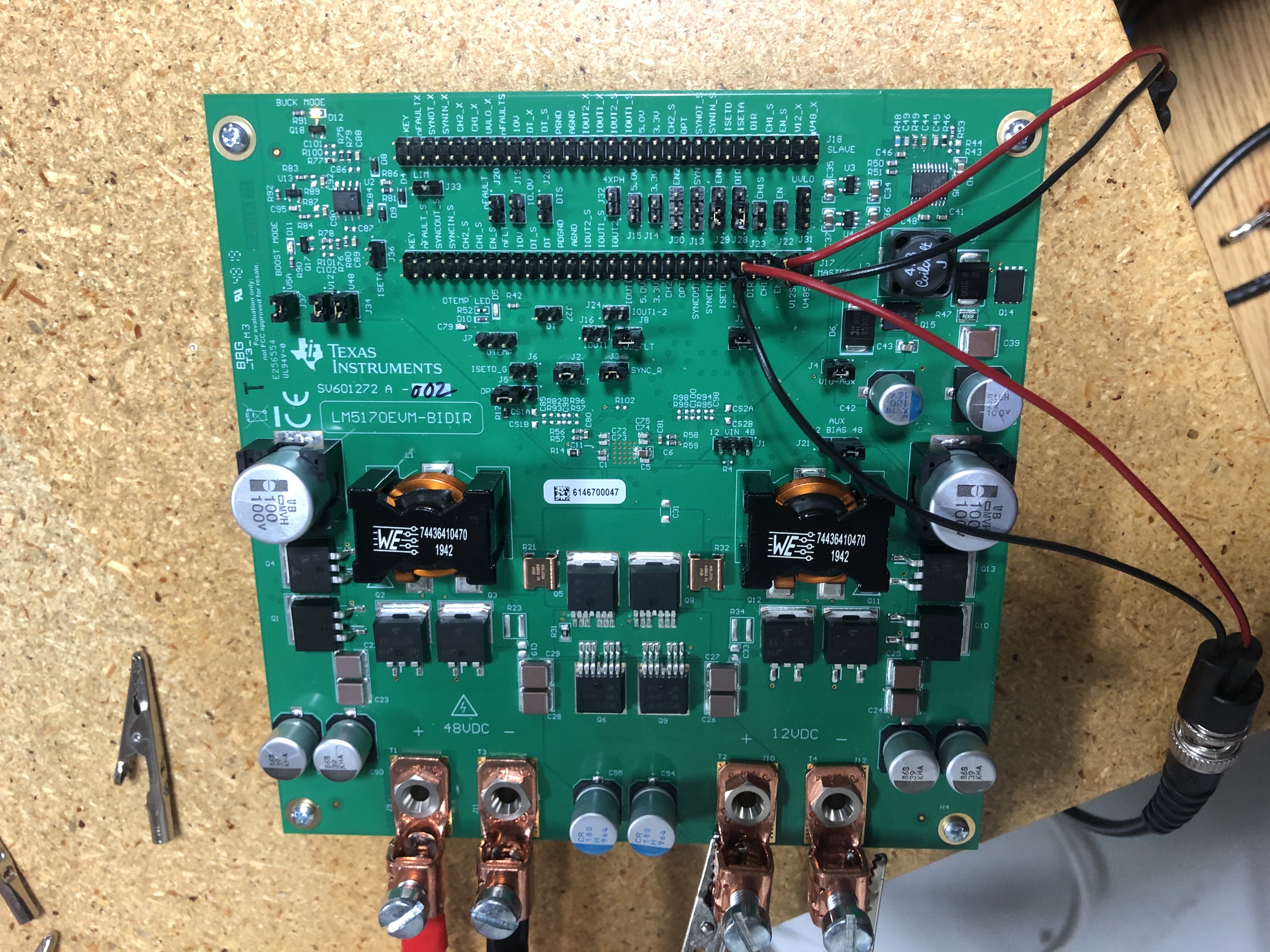
Recently, I tried to test the LM5170EVM-BIDIR in the Buck mode for my project. However, I failed to make it work properly. Please help me check the circuit attached in the picture.

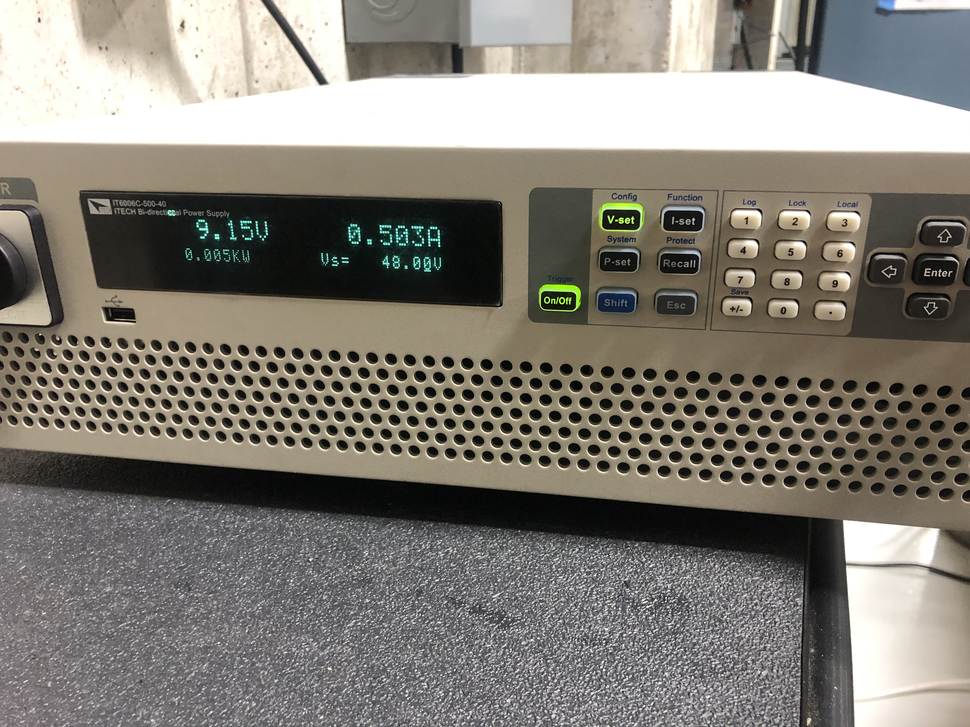
The HV-PS is connected to a DC power supply and the voltage is set at 48VDC. The LV-E-Load is connected to a Electronic Load. 

There is only one condition that the board can work. The LV-E-Load is set at around 5.5V, and the HV-PS is set at 48V and 0.5A, and they are both set at constant voltage mode. The Buck mode can operate as shown in the pictures. But the HV-PS is forced to 10V and CC mode.

Sometimes, when I turn on the HV-PS, the Buck mode LED flash for one time and the voltage cross the 12VDC port will surge to 11V, and then decrease to zero slowly.

  • Hi Chao Jia,

    Thank you for using the LM5170.  What do you really want to do?  Do you want to set your load in CV or CC? 

    Thanks,

    Youhao Xi, Applications Engineering

  • Hi Youhao,

    Thanks for your reply. For my project, I want to charge and discharge the battery at the LV ports.

    At this moment, I would like to test the buck mode of LM5170 first based on its User Guide. When I set my E-load in CC, the board doesn't work. When I set the E-load in CV with the value of 6V, the board can only operate in this condition.

  • Okay, please do the following:

    • Install 49.9k resistor at R4 (which is next to the big inductor on the right)
    • Place a jumper header on J1, closing pin 1 and 2 (the two pins on the right side, namely the 48V side)
    • Place a jumper header on J36, which is in the upper left corner of the PCB, next to J34.
    • Remove your wires on J37. The EVM will automatically start once your 48V is applied.

    Good luck on your testing.

    Thanks,

    Youhao

  • Hello Youhao,

    Thanks for your help.

    I follow the steps you list, but the board still doesn't work and the Buck Mode LED has no any light. 

    When I apply an external 10-V bias supply between J17-Pins 43 and 44 and disable the onboard 10-V bias supply, the Buck mode LED lights. I don't turn on the HV-PS, but there is a 8V voltage cross the 48V ports. Is this correct or not?

    Best regards,

    Chao

  • Hello Chao,

    Please double check your jumper settings.  Compare with the following diagram.  If the circuit still does not work, you may have damage on the EVM.

    LM5170EVM Jumper Setting for Buck.pdf

    Thanks,

    Youhao

  • Hello Youhao,

    Thanks for your help. It still does not work. The board is probably damaged. 

    Best regards,

    Chao

  • Hi Chao,

    Sorry somehow there was an error in the jumper sitting picture that I attached last week. I might have unintentionally moved the jumper during editing.  Please try again with the following diagram:  the correction is at J21, the Aux Bias, which is next to the big inductor on the lower side of the board in the picture.  It should be connected to the 48V rail.  If the circuit still does not work this time, then you have a damage on the EVM.  Sorry for the confusion.

    5808.LM5170EVM Jumper Setting for Buck.pdf

    Thanks,

    Youhao

  • Hi Youhao,

    Great thanks for your help! Unfortunately, this evaluation board does not work. I think it has been damaged. I have bought a new board, and the buck mode works very well.

    Now, I would like to test the boost mode. For my project, the input of LV side is 24V ~ 14V. The desired output of HV side is 40V. I want to control the output current from the HV side. I have several questions after I read other questions on the forum.

    1. Do I need to change any resistors on the evaluation board? 

    2. Do I need the copper foil to short the MOSFET breaker on back of the board?

    3. Could you show me the jumper connections? I would like to make sure that my connection is correct and I will not damage the board again.

    Best regards,

    Chao

  • Hi Chao,

    Thank you for the updates.  To your questions:

    1. you need to change R77 to 2.61k to set 40V boost output voltage.

    2. yes, you do.

    3. The same jumper connections like in the buck mode except for J28 that sets DIR. The header position needs to move to the other side of the J28.   

    Thanks,

    Youhao

  • Hi Youhao,

    Great thanks! 

    One more question. Do I need to install a resistor at R4 for the boost mode?

    Thanks,

    Chao

  • Hello Youhao,

    Thanks again for your help. Based on your suggestion, the boost mode works pretty good with or without the analog voltage loop control.

    Chao

  • Yes, you do if you want the circuit to start up automatically once the source voltage is applied.  We did not install it at factory because some users may have a dedicated master enable control.   If you don't have R4, you will have to supply a signal to pull up the UVLO pin to be higher than 2.5V.

    Thanks,

    Youhao