This thread has been locked.

If you have a related question, please click the "Ask a related question" button in the top right corner. The newly created question will be automatically linked to this question.

LM3435: Low current load application and switching frequency selection

Part Number: LM3435
Other Parts Discussed in Thread: LM3549

Hi,

Currently our application has max current load <400mA.  For such small current load application, would there be any side effect of using LM3435?  Or there's any design concern we should consider specifically?

in parallel, we currently configure RT pin to generate a switching frequency around 500khz and got obvious EMI issue.  How should we consider to choose a propose switching frequency or how can we add filter circuit on SW node to improve this?

Thanks!

Antony

  • Hi Antony,

    For Q1:

    the 400mA application situation will be OK.

    For Q2:

    Decrease the switching frequency will reduce the EMI issue. Could you provide more details about the EMI issue and then I can give more suggestions?

    Best Regard 

    Monet Xu

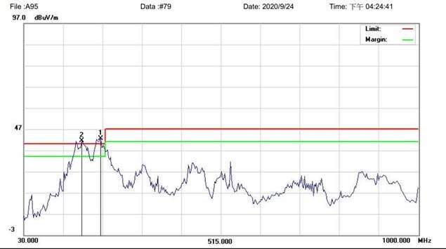
  • HI Monet,

    Regarding EMI issue, please check the result as below.  In parallel. there're some further questions.

    1. Why we suggest to reduce switching frequency?  What will be the frequency value we suggested?
    2. Customer would try to increase switching frequency so that the harmonic is moved to higher frequency.  What is your thought about this?
    3. Since their application has current load <400mA, they'll modify their resistor value on IREF pin accordingly.

    Thanks!

    Antony

  • Hi Antony,

    1. the increasing switching frequency will leads to the more EMI issue.

    2.if you try to increase switching frequency, a filter can be designed to eliminate high frequency signals and the size of design will be lager than before.

    3.the nominal maximum LED current is governed by the equation in below: ILEDx = 24.75/RIREFx * 10^3

    could you please tell me that what are the corresponding curves in the chart?  the EMI issue happed in which output signal?

    Monet Xu

  • Hi Monet,

    Regarding the EMI issue, they just confirm the EMI appears when the LED function is enabled.  This is checking through a EMI scanner aimed at their system.  They currently have no idea which signal(s) is directly linked to the EMI noise seen on the curve provided previously.  Do you have any specific suggestion regarding what kind of test can be performed to identify the noise source better?

    Regarding the EMI filter you mentioned, would you propose where and how they should implement such filter?

    In parallel, for different combination of inductor value & switching frequency, how seriously would it impact the power efficiency?

    Thanks!

    Antony

  • Hi Antony,

    Would you mind tell me that for which application do you use the LM3435 and I can give more detail suggestions?

    The LM3435 integrate a synchronously rectified non-isolated Flyback converter. An external resister connected from VOUT to the RT pin sets the main MOSFET on-time, determine the switching frequency. The programmable converter switching frequency up to 1MHz, which is the initial cause of the EMI issue. Please take care of here.

    Before the EMI filter, the following steps you can have a try:

    1. the L1 and SD1 should be as close as possible to the SW pin.
    2. The PGND connection to CIN and VOUT connection to COUT should be as short and direct as possible with thick traces
    3. The inductor should connect close to the SW pin with short and thick trace to reduce the potential electromagnetic interference.

    If the EMI issue affect the LED circuit output, a filter is useful. If the EMI issue affect the other circuit part, a shield is better.

    According to your design requirements, choose the suitable frequency balance the EMI issue and power efficiency.

    In addition, according to your description, I think LM3549 is also a suitable LED driver, which is more cheaper and easy to use.

  • HI Monet,

    Thanks for your comments.  The application is an AR.

    Antony

  • Hi Antony,

    The LM3549 is a high power LED driver with up to 700mA output current which is more suitable for your application. its input voltage range 2.7 to 5.5V. it has three constant current LED drivers and a buck SMPS for driving RGB LEDs with high efficiency.  Different from LM3435's flyback converter, it integrated buck-boost converter and just connect a inductor between the L1 pin and L2 pin. the following attached file is the datasheet for reference.lm3549.pdf

    Please contact me if you have any questions.

    Monet Xu