Hello, I modified my standard circuit, by adding the schottky diode and capacitor.
Now, I calculated the capacitor to be max. 4.3 uF ( My R1 + R2 = 173k)
I added a 22uF ceramic capacitor instead, and the detection is working perfectly. I cannot seem to find an upper limit. it works OK with 470uF still.
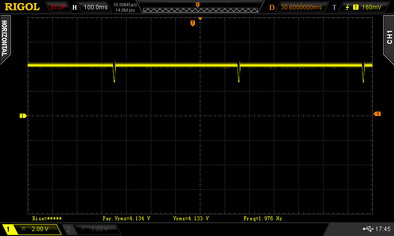
I inluded a scope picture, with the 22 uF mounted. It is measured on the battery terminal, with the battery absent.
Now, a question about the Application note:
Below picture 9 of the AN is written: Placing an appropriately sized capacitor at VD+ allows this voltage to reach VLOWV at the appropriate time in the battery detection scheme.
Now, the VLOWV = 1.55 Volt. But I think it is incorrect, because the voltage on the battery terminal is higher, because of the resistor-divider R1/R2. In my circuit is divides by two. So I guess the VD+ voltage needs to drop below 2*1.55 Volts = 3.1 volts?
So, the numbers of the equation should be , in my case:
• VLOWV = 3.1 V
• VREG = 4.2 V
• tDSCH = 1 second
am I right?
Or do I really have to use the values of the datasheet?
IF you look at the picture, do you think it is safe to use the 22uF cap?