This thread has been locked.

If you have a related question, please click the "Ask a related question" button in the top right corner. The newly created question will be automatically linked to this question.

Selecting a LI-Po charger with 3A pass through

Other Parts Discussed in Thread: BQ25895, BQ25792, BQ25713, BQ25611D

I am trying to find a charger ic that can pass at least 3A from the the input to the the system.

Ideally the current could be passed without going through the battery, to reduce battery usage. (improve general lifetime length of the battery)

My application: A battery device that monitors and keeps other systems connected charged. All systems are connected via USB, and the device is changed by USB-C or AC adapter. Only 15W so no USB - PD necessary.

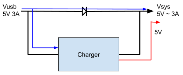
I need a chip that can provide ~ 3A to the system when plunged into a charging method, (usb or adapter) then when the devices are using less current (charged or not drawing max current) it will enable charging the internal Li-Po battery. This will be controlled/ managed by the processor, so I2C is necessary.

Dual input is not necessary, (just a bonus) because the power sources can be joined.

The BQ25895 appears like it could fit the bill, or maybe there is a better part/solution I have missed?

The LTC4155 seems to work, I am curious if Ti has a similar chip?

No BGA (saw you guys have a new similar chip in BGA)

Any thoughts / insight you guys may have I would be happy to hear.

  • HI Jonas,

    BQ25895 is one option.  Another is BQ25611D.  TI doesn't make chargers with only external battery FETs, i.e. we make controllers like BQ25713 with all external FETs but not controllers.  You might also consider BQ25792.   

    Regards,

    Jeff

  • I would actually prefer internal FETs,

    For the application, I need most of the 3A to be delivered to the system when power is connected. When the end devices are charged, the battery charger can be enabled to top up the battery.

    I like the the BQ25895 but since it provides 3.1A 5V as a OTG output, I am concerned that it can not provide that while connected to Vusb.

    The BQ25713 looks like it would accomplish this, I am curious if there is a more integrated solution

    Essentially a charger that accomplishes the very theoretical diagram below

    blue being external power (when Vsys is drawing ~3A charging would be disabled )

    red being discharge of the battery when no external power is connected.


    Thanks for your help

    Jonas

  • Jonas,

    We are checking and will get back to you.

    Thanks,

    Ning.

  • Hi Jonas,

    The SYS output for all of TI's LiIon NVDC chargers cannot be set to a fixed output voltage.  It can be set to a minimum system voltage, to allow the system to power up with depleted battery, but will eventually follow the battery up as it charges to maximum (4.2V, 8.4V, 12,6V, etc.).  BQ25895 is the only charger currently available that was designed to have a  "system" load at PMID. So, you can place USB 5V at VIN and get 5V-IPMID*Rdson at PMID pin.  When VBUS goes away, there are 10's of ms delay before the charger can change over from charge to OTG mode and regulate PMID to 5V.  

    I will follow up with our development team and get back to you if there is a product coming soon that can do this.  But, most likely, there will be a delay before the converter can switch from forward (charge) mode to reverse (OTG) mode which will cause a dip in the 5V rail.

    Regards,
    Jeff

  • Thanks Jeff and Ning

    I was not thinking of it that way, the block diagram makes more sense now!

    So does that mean PMID will follow Vin when external power is applied? If so, what is the current limit of PMID, still 3.1A?

    Ex. If 12V is applied at Vin, would Vpmid = Vin - Ipmid**Rdson, if so, could PMID supply ~12V at ~2A (only during external power)

    "slow" switchover is okay for our application, each external device has a battery of some sort

    I am interested to hear if any new ic is in the works.

  • Hi Jonas,

    The FET between PMID and VBUS is used for current sensing and reverse blocking only so PMID follows VBUS.  There is no current limiting from VBUS to PMID, as current limit in either forward (charge) or reverse (OTG) mode is performed by limiting the converter duty cycle.  If a load pulls current from PMID in forward (charge), the charger's converter is "starved" and may have to rely on the battery to supplement the SYS load.

    Regards,

    Jeff

  • Thanks Jeff for the help.

    I have a much clearer picture of this chip

    Did your inquiry for a new product turn up anything?

    possibly having a greater input voltage

    I will resolve this issue on your 2nd reply, as I think it best answers the original post

  • Dear Jeff,

    about the time delay you written tha is equal to 10 ms I kindly request some clarification because into the BQ25895 datasheet (may 2018 / point 8.2.5) I can read that the boost is enabled after 30ms delay from boost mode enable, then it appear to me that the delay time needed to enter into the boost mode operation from battery should be at minimum 30 ms... could you please let me know more about this point?

    Thank!

    F.

  • Hi Fabio,

    The delay before the boost converter can provide a voltage at the PMID pin is 30ms per the datasheet.  Until then, the voltage at PMID (assuming no power source connected at VBUS) is V(BAT)-Vdiode. 

    Regards,

    Jeff

  • Thank Jeff!