This thread has been locked.

If you have a related question, please click the "Ask a related question" button in the top right corner. The newly created question will be automatically linked to this question.

BQ77915: SCD Delay

Part Number: BQ77915

Dear Forum,

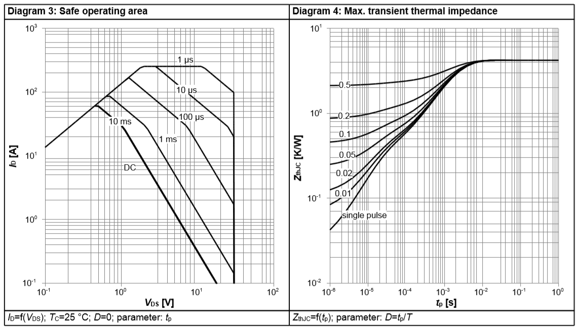
I would like to ask why '77915 SCD so long (1msec)? My MOSFETs burned out:( (I did not checked the safe operating area only the peak pulse current).

My experience, using PowerSO-8 (TDSON-8) MOSFETs and 5 cell design, one series FET switch circuit not enough due to long reaction time (overdisspation).

In other words, if SCD were shorter single (or smaller) FETs could be used.

In case of stacked application (higher voltage->larger short current) using parallel FETs is mandatory, however application note does not mention it.

The voltage on the FET ca 2V (voltage divider action between Rdson and pack + short resistance). I think 50..100us SCD would be accepted.

Can I reduce SCD reaction time allowing to use singel FETs because my board space very limited (no place for parallel FETs..) 

Joseph

  • Hi Joseph,

    If you are interested in multiple FETs, you can check out this app note.

    The SCD can be either 0.96 or 0.4 ms, depending on what version of the device you are using. This is fixed in the programming and cannot be changed by the user. 

    The only thing you could change is the CHG and DSG FET rise and fall times, this is outlined in section 10.1.1.1 of the datasheet. However, it will probably not be able to get down to 50 or 100us.

  • Hi Shawn,

    thank you for the information. 

    One question about parallel FETs: whay CHG control path is speeded up by using active gate charge pull out circuitry? I would apply this idea for DSG because if pack shorted

    the DFET should be OFF quicky (if CFET channel is OFF, its body diode still conducts in case of loading, it has affect in charge direction...)

    Meantime, I experienced a strange bahaviour:

    something happened (during FET burn-out or measuring the board, but FET has been replaced, no short on the PCB) because DSG working (12V gate) but CHG is not. Note, when, I connect a load, the CHG line goes up to 12V and goes back to 0 when remove. CFET should be OFF when protection event occurs (NTC, OV, OC) but evertyting seems to be OK (all cells are 4,12V, NTC 10K).

    Maybe I forget some condition whicj blocks CFET.

    On the NTC voltage divider there are pulses when checking by scope. It seems the BQ want to start but is not able.

    Joseph

  • Hi Joseph,

    Both CHG and DSG can be changed, if you are only worried about one specific fault then you do not have to change both.

    If the CHG FET is off, then I would recommend looking at Table 9-5 in the datasheet. This table describes each fault of the device and the response of the FETs. I would recommend going through each row of the table and making sure none of these conditions are present.

    Yes, the NTC does pulse to check the temperature. This is normal behavior.