This thread has been locked.

If you have a related question, please click the "Ask a related question" button in the top right corner. The newly created question will be automatically linked to this question.

UCD3138: Questions about UCD3138 PMBus Timeout Difference

Part Number: UCD3138

SMBus 2.0 specification

SMBus 2.0 specification: http://smbus.org/specs/smbus20.pdf
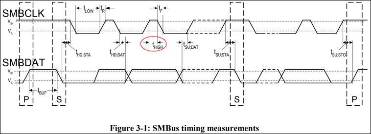
The following figure is taken from the SMBus 2.0 specification, Page 11, Figure 3-1: SMBus timing measurements
 The following figure is taken from the SMBus 2.0 specification, Page 13, Figure 3-2: Timeout measurement intervals

The following table is extracted from the SMBus 2.0 specification, Page 11, Table 1: SMBus AC specifications

UCD31xx Digital Power Supply Controller - PMBus Interface/I2C Interface

File Title: UCD31xx Digital Power Supply Controller, Literature Number: SNIU028D FEBRUARY 2016 – REVISED SEPTEMBER 2020
File URL: https://www.ti.com/lit/ug/sniu028d/sniu028d.pdf

The picture below is a screenshot from the description of the file content (Page. 386), Clock High Timeout Detection

The following figure is a screenshot from the description of the file content (Page. 419), Table 10-7. PMBus Status Register (PMBST) Register Field Descriptions (continued)

Question

Hello Experts,

  1. Does the function of CLK_LOW_TIMEOUT correspond to the TTIMEOUT specification in the SMBus 2.0 specification?
    And please explain CLK_LOW_TIMEOUT detection working principle.
  2. TLOW:SEXT, and TLOW:MEXT in the SMBus 2.0 specification. Is there any corresponding function support in the UCD3138?
    And please explain detection working principle.
  3. In the document file, (Page. 386) and (Page. 419), why are the units of Clock High Timeout Detection different?

Thank you very much for your reading and answer.

  • Hi, your question is forwarded to an expert, please allow some time to get back to you.

  • The UCD hardware will reset the PMBus and set the clock low timeout flag after about 35 msec of clock low, as required in the SMBus 2.0 spec.  

    That's the working principle of the clock low timeout.  If the clock is low for 35 msec, it will reset the PMBus interface.

    There is no hardware support in the UCD3138 for the cumulative clock low timing.  It's not required to be detected.  You should be able to prevent these things from happening by good firmware design to make sure that the PMBus hardware is serviced properly.  The PMBus hardware will essentially respond at the set clock speed with no extra clock stretching until it needs the firmware to read, write or acknowledge something.  The clock will be stretched at that point, so you need to make sure that the firmware responds in a timely manner.  It's not very hard to do so quickly.  

    I'm not sure why the clock high timeout is the way it is.  There's no PMBus requirement to detect the clock high, just a requirement to keep it short placed primarily on the master.   The parent of our PMBus hardware was specified by a specific customer, so this may have been their enhancement to the default spec.  I have actually never seen an issue with clock high being too long, and I've been working as the lead PMBus applications engineer on the UCD families since they were introduced.  

    None of our firmware uses the clock high timeout.  

  • Dear Ian

    Thanks for the reply and it’s really helpful for our design.

    Can you help to share some reference or example if we want to detect the cumulative low timeout?
    We need to achieve this required but not kindly understand the principle and how to do on the UCD3138.

  • There is no requirement from the PMBus that you detect this.  You just need to avoid exceeding it.  As the slave, it's very hard to measure your contribution to the delay.  You are dependent on the master clock timing, and lag.  At most you can only really see when each byte comes in, so you could measure the time for each byte.

    To do that accurately, you would have to use the fast interrupt to ensure fast response to the PMBus hardware, and you would could sample the 24 bit timer which is free-running - basically a time base.  You could measure the time between each byte, and make an assumption about how fast the master is clocking each byte.  Then subtracting your estimated byte time from the total time between each byte would give you the approximate clock low time.  Then you could add that up for the whole message.

    This would increase your processor overhead for the PMBus significantly, Normally we use auto address and command ack, and allow up to 4 bytes to be received into the 4 byte buffer.  This means that a 1 byte message takes only one read to handle it all.  And normally we poll the PMBus interface, rather than using the interrupt.  With this technique, we still stay well below the cumulative clock stretch requirement.  We do this in background mode.  This way we are actually using the clock stretch to protect the power supply control functions from being overloaded by a high rate of PMBus messages.

    If you go to single byte detection, you will have to separately detect:

    1.Address

    2. Command

    3. Data

    4. PEC

    5. Stop

    f you give the fast interrupt to the PMBus, it could possibly interfere with the power supply control functions, especially if you are doing the PMBus command processing and activity in the fast interrupt.  

    Instead, I recommend just using an I/O line to see how fast you are polling the PMBus, and make sure that it is significantly faster than 25 msec.