This thread has been locked.

If you have a related question, please click the "Ask a related question" button in the top right corner. The newly created question will be automatically linked to this question.

BQ24091: BQ24091

Part Number: BQ24091

Hi,

I want to use BQ24091 to charge 3.7v 2500mAh lithium ion battery. My queries are:

1.In Datasheet BQ24091 out voltage is 4.2. Can i use 4.2 OUT voltage output to charge 3.7V battery placed in J11 connector place. by using 540mA fast charge current.

2.Is it right to interface #CHG to micro controller GPIO to read the status of charging and charge complete. If i can when will i get logic 1 and logic 0. 

3.Is it right to interface #PG to micro controller GPIO to read the status of power good or not? or does PG pin has other functions. I have not understood PG pin info. from datasheet

4.Suppose lets think the battery has charged to its maximum capacity does BQ24091 stop supplying/charging  the voltage to battery or it continuously supply the charge until i remove power source.

5.6.6V Over-Voltage Protection is present in IC but my battery is only 3.7 does the battery fail/explode because my battery is only 3.7 (or) does the IC detect that  battery is fully charged.

6.Do i need to specify my battery voltage capacity to BQ24091 

7 Does BQ24091 have provision to disconnect/cut/stop the battery charging from my controller can i do that?

  • Hi Akhil,

    Welcome to E2E!

    To answer your questions:

    In Datasheet BQ24091 out voltage is 4.2. Can i use 4.2 OUT voltage output to charge 3.7V battery placed in J11 connector place. by using 540mA fast charge current.

    Yes, this is the typical voltage used to charge lithium ion batteries. The fast charge current is normally 1-2 times the capacity of the battery. It’s best to check the battery datasheet but these should be fine.

    Is it right to interface #CHG to micro controller GPIO to read the status of charging and charge complete. If i can when will i get logic 1 and logic 0. 

    Yes, by connecting a pull-up resistor between the microcontroller’s power rail and the /CHG terminal, you’ll be able to read charge status from the pin.

    Is it right to interface #PG to micro controller GPIO to read the status of power good or not? or does PG pin has other functions. I have not understood PG pin info. from datasheet

    By connecting a pull-up resistor between the processor’s power rail and the PG terminal, you’ll be able to monitor whether the input voltage is above UVLO and OUT (battery voltage), which results in a LOW logic on the /PG pin.

    Suppose lets think the battery has charged to its maximum capacity does BQ24091 stop supplying/charging  the voltage to battery or it continuously supply the charge until i remove power source.

    Once the battery is fully charged, the BQ24091 will stop charging the battery. Once the battery drops below the recharge detection threshold (which is about 4.1V), the battery will charge the battery again.

    6.6V Over-Voltage Protection is present in IC but my battery is only 3.7 does the battery fail/explode because my battery is only 3.7 (or) does the IC detect that  battery is fully charged.

    The over voltage protection is in regards to the input voltage. If the input voltage source applies an overvoltage, the device will turn off and stop charging once it after t. Once the voltage returns to normal, charging will continue.

    Do i need to specify my battery voltage capacity to BQ24091 

    Nope, this is all covered by the BQ24091 based on the voltage that it reads at the OUT pin.

    Does BQ24091 have provision to disconnect/cut/stop the battery charging from my controller can i do that?
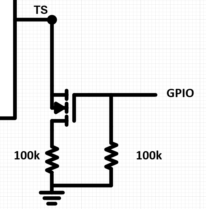
    If you are not using the TS pin with an NTC, you can control the TS pin by pulling the pin low. To maintain normal operation, you can pull pull the device to VSS with a 100k resistor. With a GPIO pin, this can be controlled with a FET.

  • Thanks for the detailed reply.

    Your explanation was very detailed and understanding.

    I am new to electronics and i have not understood the last part of connecting it with a FET.

    Will you please provide a picture of how to interface it to my controller if possible or any reference so i can copy that.

    I want to have the TS pin normally to GND and if needed i want to make it high using controller GPIO pins to disable the ic.

    Connecting a 100K between TS pin and GND and connecting the node point of 100K and TS directly to controller GPIO pin will work? Or will it damage the controller if have not used any FET in between.

    As you can see from schematic i have placed two resistor and gave the point(TP10) to my controller ADC pin to monitor how much charge is present in my battery. Is it a right way to do it or do i need to use a fuel gauge IC again like BQ27441-G1A to get my battery information.

    Regards

    Akhil.

  • Hi Akhil,

    Your idea will only work if you're GPIO does not pull the voltage when wanting to be in the CHARGE state. The concern is that the BQ24091 will not be able to properly operate when the GPIO is not pulling the pin low (unless you are able to leave the GPIO pin in a floating state).

    The FET can be used create a current path to GND instead of the resistor and be voltage controlled by the GPIO. 

    I will provide an imge by EOD. 

  • Hi Akhil,

    Attached is the what I can give to understand the GPIO control. When you apply a high voltage at GPIO, the TS pin will be connected to the 100k resistor to GND. When the GPIO is low, the FET will be open and the pin should be left floating. 

  • Hi,

    Thanks for the picture i will use it my design.

    You haven't answered me on ADC part of the question.

    As you can see from schematic i have placed two resistor and gave the point(TP10) to my controller ADC pin to monitor how much charge is present in my battery. Is it a right way to do it or do i need to use a fuel gauge IC again like BQ27441-G1A to get my battery information.

    Regards

    Akhil.

  • Hi Akhil,

    As these are connected to the output and will have a non-zero voltage, charging will be affected and termination may not be accurate. Both options are fine there are just some drawbacks this way.