Because of the holidays, TI E2E™ design support forum responses will be delayed from Dec. 25 through Jan. 2. Thank you for your patience.

This thread has been locked.

If you have a related question, please click the "Ask a related question" button in the top right corner. The newly created question will be automatically linked to this question.

SG3524: Not able to achieve the output required

Part Number: SG3524

Hello,

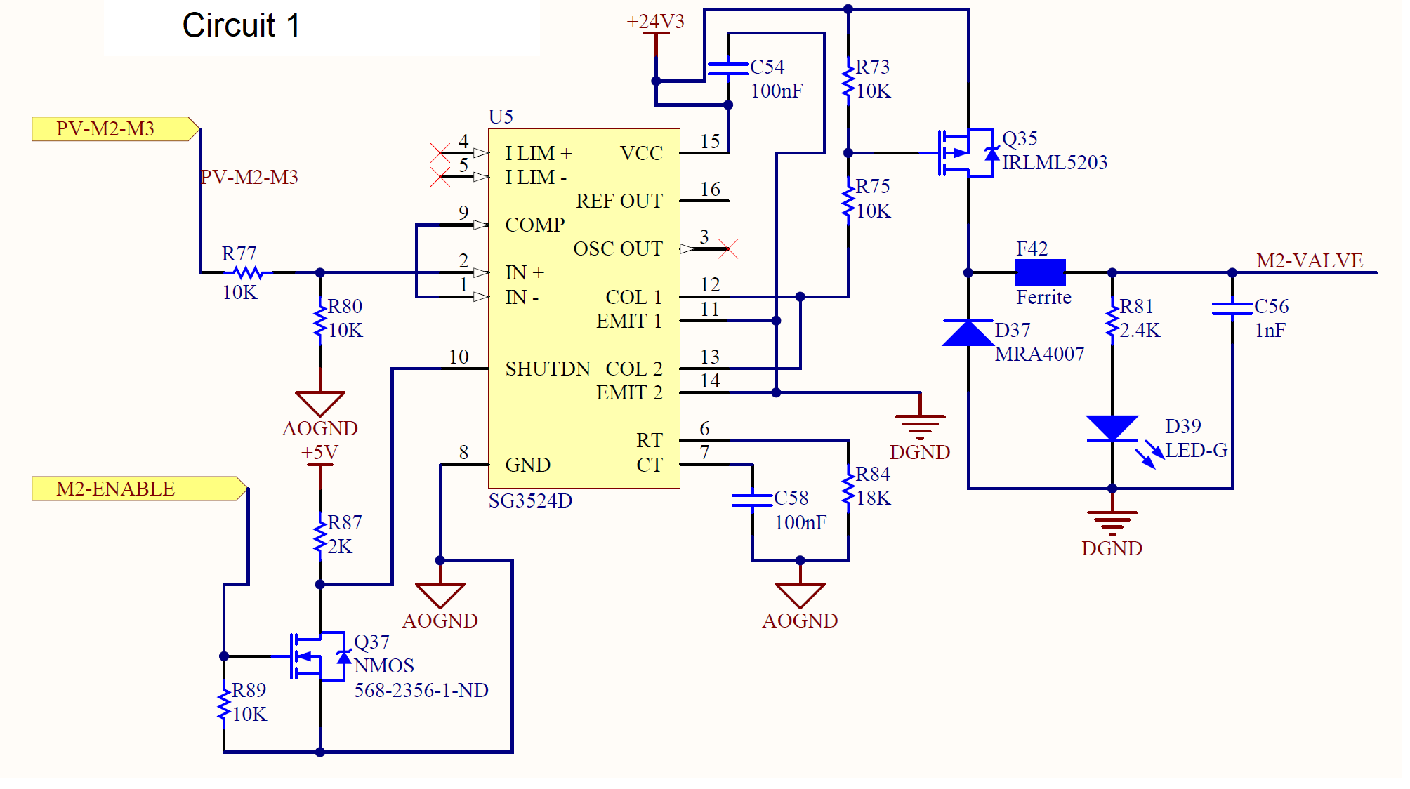
I've been using SG3524D in one of our designs and it works well to control the proportional valves. Below is the circuit.

The enable signal is 5V and the Input is 10V.

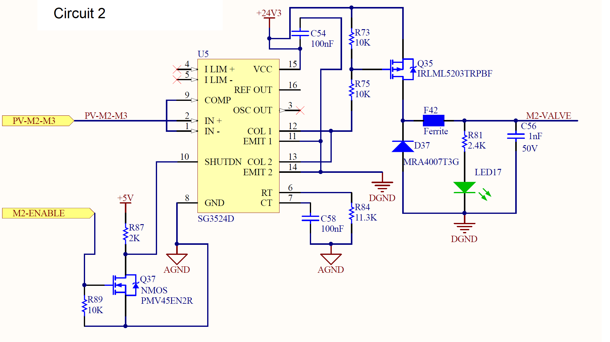
Now I made a slight change to the circuit since the input to the circuit is reduced to 5V. I removed the voltage divider to the input and also changed R84(RT) to drive a faster frequency valve ( Power specs are same as the old valve).Those are the only differences, but this circuit cannot output the required voltage to the valve. Below is the new circuit. Can you think of any reason why this would happen. Please help me understand if I'm doing something incorrect. Thanks.

  • Hello,

    I did some bench tests and when I used an external voltage divider at the input, the circuit works as intended. Is there an input impedance requirement for the inputs?

    If so, are there any workarounds without the resistor divider network.Please let me know.

  • Hi,

    If there is divider, the divider resistor to IN+ parasitic capacitance forms like a filter. If there is no divider the filter is not there. I suspect the suddenly adding external 5V to IN+ especially before the IC is biased ok, it may cause possible latch off.

    Why cannot you add the divider back?

  • Hello,

    Thanks for thr quick response. Yes I can add the resistor divider network back.

    However, if there is an alternate fix for now, I want try to it and add the resistor divider network in the next revision of the board.

    I've tried an external resistor in series to the IN+. I've tried a 200 Ohm, 500 Ohm and 1 K Ohm resistance at separate instances. It works with the 500 Ohm, 1 K ohm resistors in series and not the 200 ohm resistor. 

    I've come to the conclusion that the IN+ needs a source impedance. Like you explained if it needs a filter at the input, just a series resistor should suffice. A resistor divider is not needed. Is this correct?

    If so, can you provide me the min and max of the resistance that I can use in series.

    Naveen.

  • Hi,

    There is no external fix. You need to add the resistor divider back. A typical range should be 2k to 25k for the divider. You may try to add a small capacitor, 10 to 47pF,  from IN+ to GND, if you want to use smaller value resistors. But it is better to use resistors with values in 2k to 25k.

  • If forming the filter is main concern then I can just use a single 2K resistor in series to the input, right?

    I don't need 2 resistors to form a voltage divider. 

    Alternate path:

    The input that I have has a source impedance of 50 Ohm. Can I use a 47pF cap from the input to the ground? Does this work?

    If a filter is the main objective, what is the cutoff frequency we're trying to achieve.

    Please let me know.

    Thanks.

  • You can try to see if ok or need to adjust but overall it is like that.