While trying to develop a series of tests to allow the electrical characteristics of the device to be tested, we found we were unable to produce any form of pulsed output as expected.
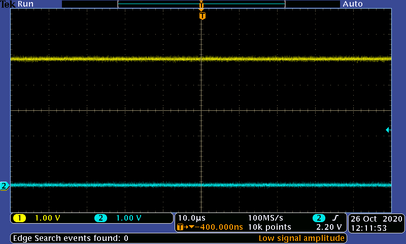
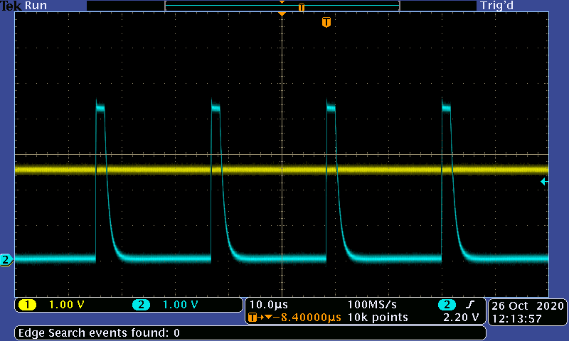
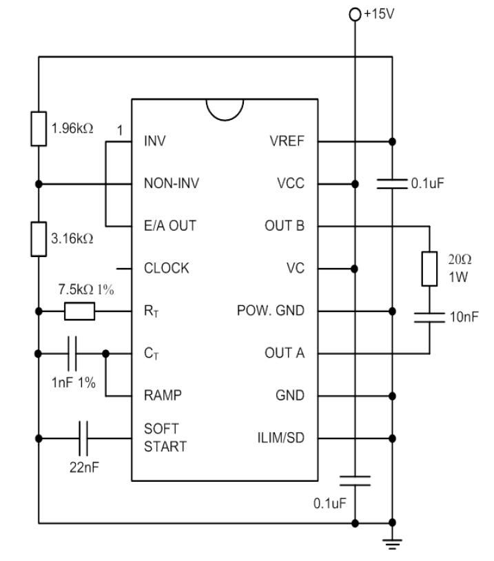
The test circuit used to test the part was the one suggested in the "Open-Loop Test Circuit" for the UC2825-EP (SGLS305D). After constructing the circuit as shown, we were able to confirm the waveforms for the CLK/LEB pin, CT pin and ILIM/SS section were functioning as expected. However the output remained at a constant near 0 (<300mV) or high (~13V).
The EAOUT pin was a DC waveform of around 120mV and therefore never crossed into the threshold of the RAMP waveform (to enable the function of the PWM Comparator (as shown in the block diagram).
Researching online we came across SLUS235A, which provided an alternate Open-Loop Test Circuit, however in a similar fashion this also proved unsuccessful with the EAOUT now showing a DC waveform of around 5V (above the RAMP) and the outputs once again being a constant voltage near 0 (<300mV).
Is there something we are doing wrong to produce the expected pulses at the output? Have we forgotten a key component of the circuit or is there possibly something wrong with the circuit diagrams we are using (possibly a printing error)?
Thank you for your time and help