Because of the Thanksgiving holiday in the U.S., TI E2E™ design support forum responses may be delayed from November 25 through December 2. Thank you for your patience.

This thread has been locked.

If you have a related question, please click the "Ask a related question" button in the top right corner. The newly created question will be automatically linked to this question.

PTH08T240W: PTH08T240W

Part Number: PTH08T240W
Other Parts Discussed in Thread: PTH08T241W

Hi,

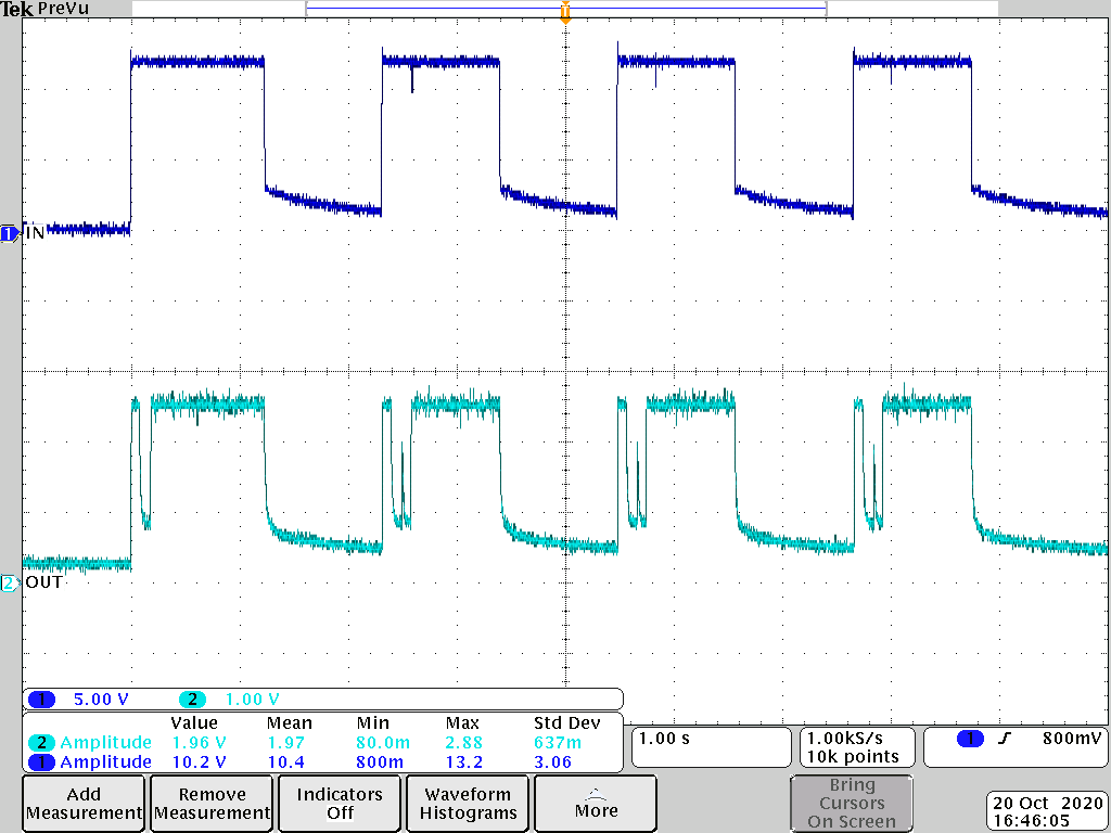
We have a problem with PTH08T240W. According to the datasheet, when RTT is short (0 Ohm), we need a high output capacitance (~2000uF). If we are using 2x100uF with ESR 5mOhm each, and 2200uF, than the module is not able to start, the output voltage is looks like the module is in short circuit protection. If I try just with 2200uF/6.3V low ESR electrolytic capacitor, the result is the same. The best result is when we are using a 220uF ceramic capacitor with 10mOhm ESR, but even in this case the module sometimes starts, than after 100ms switch off, than after 100ms switch ON again. The input voltage is 12V, the output is 2.5V, 1.6A.  With 2x100uF ceramic capacitor (5mOhm ESR) + 470uF (ESR 150mOhm) the module starts after 5-10 100ms cycle.

Three times power ON/OFF:

  • Only 2200uF/6.3V

  • Hi Attila,

    It looks like the input voltage is also dropping in this waveform after ~1 second. Is your input source getting current limited?

    However, before the input voltage drops for ~1 second, it does look like the module may be tripping and restarting like it is hitting its overcurrent protection. However we might be missing drops in the input voltage due to the relatively low sample rate in this waveform.

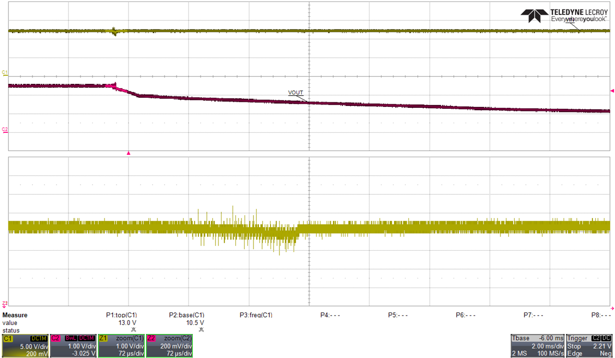
    Could you retake this waveform zoomed in on the first startup attempt using a lower time scale and a much higher sampling rate? Maybe with a timescale around 10ms and a sample rate of at least 10 MS/s.

    Anthony

  • Hi,

    The input has 10A current limit.

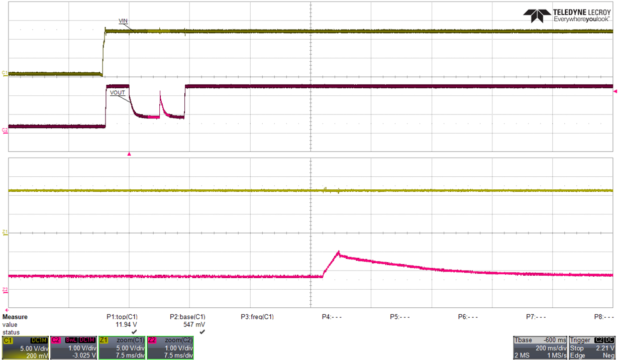
    "it does look like the module may be tripping and restarting like it is hitting its overcurrent protection"  yes, this is the problem. The power supply was switched ON/OFF, to show, that at every startup we have this behavior. These are the new waveforms:

  • Hi Attila,

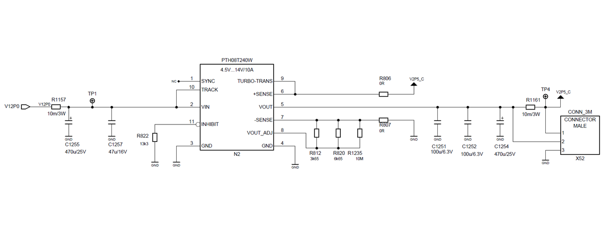
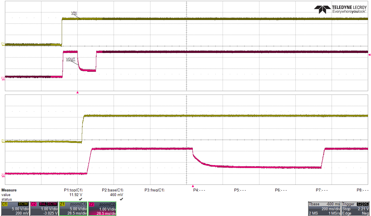
    Thank you for the zoomed in waveforms. This definitely verifies the issue shouldn't be with the input source. Do you have some input capacitance local to the module? They are cut out of the schematic image you had posted.

    I'm also trying to better understand the capacitance you are using in this testing. With RTT = 0Ω, it is required to have at least 1500µF Cout when using Type A, at least 1100 µF when using Type B, and at least 2000 µF when using Type C. Also, when using the PTH08T240W, there is a minimum ESR requirement of 7 mΩ. So when using turbo trans with the PTH08T240W, the allowed output capacitors is narrower than with the PTH08T241W.

    When using the 2x 100µF with 5mΩ + 470µF with 150mΩ, the effective ESR may be enough for stability with the combination but it doesn't meet the minimum output cap requirement for RTT = 0Ω. I think this combination would be similar to Type B output caps, so if you used 4x 100µF and 2x 470µF it may meet the stability requirements.

    When using 1x 220uF with 10mΩ, the effective ESR requirement is definitely met but again this isn't enough capacitance to meet the minimum output cap for RTT = 0Ω. If you used 5x of these caps it would satisfy the minimum ESR and the minimum cap.

  • Hi,

    This is the full schematic:

    And this is the start-up behavior with 5x220uF  JMK325ABJ227MM-P:

  • Hi Attila,

    Sorry I just noticed I had a typo in my previous post. I meant to say the issue shouldn't be with the input source.

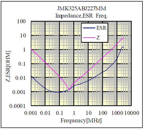
    The https://ds.yuden.co.jp/TYCOMPAS/eu/detail?pn=JMK325ABJ227MM-P&u=M doesn't meet the minimum 7mΩ ESR requirement. Below image is the impedance and ESR vs Freq curve and it looks to be around 2mΩ ESR. For the ESR, use the ESR at the frequency where the ESR sets the impedance which is between 400-500 kHz for this capacitor. Below this frequency the capacitance sets the impedance and above this frequency the inductance sets the impedance. With low ESR ceramic caps like this, you would need to use the PTH08T241W instead to meet the stability requirements.

    What capacitor options do you have for modifying this design? If you would like to use only low ESR ceramics, the PTH08T241W should be used if that's an option. If you would like to use a mix of low ESR ceramics and higher ESR aluminum caps, you might be able to get combination to work with the PTH08T240W but you would need the majority of the output capacitance to come from the higher ESR caps.