This thread has been locked.

If you have a related question, please click the "Ask a related question" button in the top right corner. The newly created question will be automatically linked to this question.

TPS27S100: Load Transient Response of Adjustable Current Limit & Thermal Shut Down Problem

Part Number: TPS27S100
Other Parts Discussed in Thread: , TPS1HB16-Q1, TPS27SA08, TPS1663

Hi there,

I'm Zeming, FAE at TI Japan.

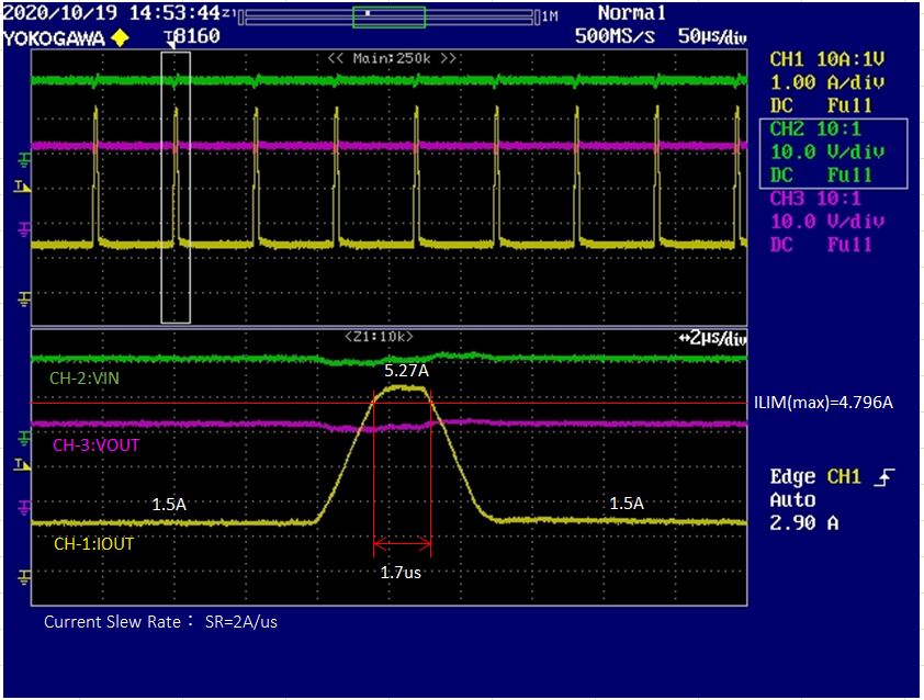
My customer is evaluating TPS27S100A using TPS27S100AEVM. He used an external resistor to set the current limit as 4A, and set load current as 1.5A⇔5.5A with 2A/us slew rate. Output was connected to a CR mode electronic load.

As you can see below, the current rose to 5.27A with almost no current limit. Was the current slew rate  too fast so that the current limit could not work normally? If  so, how long is the response time of current limit?

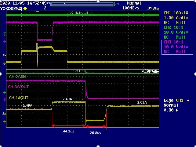
Also, when he tried the condition of VIn=24V, Iout=3.3A(continues) with CR mode electronic load, thermal shut-down occurred. Output voltage and current was clamped to 50%, and ON/OFF operation happened repeatedly. 

I calculated the junction temp using the thermal resistance, but it seems to be not beyond the TSD temp. Why did this happened? and what is the largest continues current when Vin=24V?

I would appreciate it if you could help!

Regards,

Zeming Kong

  • Hi Zeming,

    The current limit protection requires an overload of 1.5x the current for datasheet accuracy to hold. The current limit feature is mainly to protect against capacitive inrush and short to GND events. 

    Some devices may show variation but the accuracy of the current limit is not specified until the overload condition meets the 1.5x threshold. This is noted in footnote 3 on the datasheet just under the current limit and current sense specifications.

    For the thermal calculation, the power equation is only for DC temperatures. Can you please retest this condition with a power resistor and not a electronic load? Please provide a waveform and schematic as well. By CR mode you mean that the electronic load was set to 7.27 Ohms? If the electronic load is set to pull 3.3A as constant current, this could be causing an excess of current through the device during turn on.

  • Hi Shreyas,

    Thanks a lot for your fruitful suggestion!

    The customer found that the electronic load he had used caused extra current during start-up, and he tried another load, the operation of TPS27S100 recovered.

    Regards,

    Zeming

  • Hi Shreyas,

    The customer has another question about TPS27S100's thermal swing function.

    He used TPS27S100AEVM at VIN=24V, ILIM=2A, a electronic load at CR mode, and set up a current pulse of 0 ⇒ 1.5A(1ms) ⇒ 2.5A(1ms) ⇒ 1.5A(1ms) ⇒ 0, SR=2A/us like below, then he found when the current up to 2.5A, the output was soon turned off, and after that, the current became 2A the same as the ILIM, but no output voltage.

    Was this due to a thermal swing operation? If so, when will thermal swing happen? Every time Temp>60℃ it happens, or when over current flows, temp sharply rises then thermal swing operates?

    Also, He needs to know why there was no output voltage after restart, which should have been 2A*9.6ohm=19.2V. According to your previous answer, I am wondering if it was due to the inrush current caused by electronic load. When the switch restarts, the inrush current flows into and Rds of TPS27S100 increases to limit it, and finally the load shows a low voltage. Is my consideration correct?

    Please help solve this problem!

    Best,

    Zeming

  • Hi Zeming,

    Please refer to Section 7.3.4.4 on the datasheet and Figure 30 on the datasheet to get a better idea of the thermal protections in this device.

    Thermal swing occurs whenever the power FET temperature increases sharply when compared to the internal controller temp. An instant pull of current could cause this. Thermal swing occurs every time the FET temperature rises too quickly.

    I assume the same situation is occurring as previously stated since the electronic load is causing too much current to flow during turn on as the setting is set to pull 2.5A. I would suggest setting the resistance value rather than the current value on the E-load. I believe that the e-load is causing too much current to flow through the FET before the FET can fully turn on(high R_ds) causing a lot of power dissipation and keeping the device in thermal shutdown. Once the current is dropped, the FET is able to recover.

  • Hi Shreyas,

    Thank you very much. Your reply helped a lot.

    I asked the customer to increase the current limit to 4A and retest, then thermal swing was not triggered this time. So thermal shutdown is also related to current limit setting? I checked 7.3.4.4 on the datasheet. Could you tell me what T(logic) is? There is no description and data of this on the datasheet. Do you have a more detailed material to explain when thermal swing will happen? The customer needs to know the specific conditions that will trigger thermal swing.

    Also could you explain why there was a 2A output but 0V voltage after the thermal swing shutdown, e-load was set as a 9.6ohm resistor here, so it should have been a 19.2V output.

    Best,

    Zeming

  • Hi Zeming,

    Current limit works hand in hand with thermal shutdown. The device limits current by modifying its on resistance. This causes the device to heat up to T_SD eventually which results in a thermal shutdown. Thermal swing can be thought of as a transient thermal shutdown. This is caused when the FET temperature rises over the logic (T(logic)) temperature by 60C. This means that there is a sudden high current pull through the device. Thermal swing prevents the FET from failing in the event of a large transient current pull .

    The output voltage will drop during a current limit event. This is because during current limiting the voltage drop across the FET is large. When the device turns off, I expect the voltage to go to 0V here. I believe that the device was unable to turn on again due to constantly hitting thermal limit until the load current was reduced.

    Please refer to Section 7.3.2 on the datasheet for information about the current limit and its relation to thermal shutdown. Please refer to Section 7.3.4.4 on the datasheet and Figure 30 on the datasheet to get a better idea of the thermal protections in this device.

  • Hi Shreyas,

    Thanks a lot for your reply.

    You have made it clear for me.

    Best,

    Zeming

  • Hi Shreyas,

    Thermal swing is a good function but, this does cause unexpected shutdown when my customer tried to apply it to their circuit so he has to decide not to use it.

    Do we have any similar device but without thermal swing?

    Best,

    Zeming

  • Hi Zeming,

    I do not believe that we have a switch without thermal swing. 

    I think another option might be to use a lower R_on device as this will heat up less.

    We offer TPS27SA08 but this device does not have adjustable current limit. Perhaps TPS1HB16-Q1 could work here?

    Version A of this device can do a CL of 4.4A at minimum.

  • Hi Shreyas,

    TPS1HB16-Q1 seems to be a good solution. But the customer needs to use it in a 24V VIN condition, will this device still be reliable even beyond the recommended range 18V? And he needs a soft start, TPS1HB16-Q1 has a 100us turn-on time but I am not sure if this is enough.

    Should I take a look at efuse lineup? TPS1663 looks good, too.

    Best,

    Zeming 

  • Hi Zeming,

    The device will be reliable outside the operating range of 18V but the fault protections may not be accurate.

    It might be beneficial to look at eFuse offerings if TPS27SA08 is not acceptable to the customer.

    If the customer is interested in the eFuse device, please create a new thread with the eFuse part number so the relevant engineer can give you faster support. Also, feel free to email me or the power switches team directly.

  • Hi Shreyas,

    Thanks a lot for your continued help!

    I will email PSIL team for further support.

    Best,

    Zeming