This thread has been locked.

If you have a related question, please click the "Ask a related question" button in the top right corner. The newly created question will be automatically linked to this question.

BQ79606A-Q1: Communication between host and bridge (UART): the last four bytes are repeated.

Part Number: BQ79606A-Q1

Hello, I am working with the BQ79606, I design a software that communicates with the bridge to read or write a register.

Actually, I can read the received message, but I don't understand why the string received by UART from the bridge repeats the last four bytes.
As I understand it, in the reception of data by UART each byte that is transmitted has a start bit that is always zero and a stop bit that is always one.
I am trying to read a device from the Stack with the command "SingleDeviceRead". The address of the stack device is 0x01.
And the record I am trying to read is the ECC_TEST record.
In the response I get I get:
| RESP_INIT | DEV_ADD | STRT_REG_ADD | STRT_REG_ADD | DATA | CRC | CRC | STRT_REG_ADD | DATA | CRC | CRC |

Here is an image of what I receive, which exemplifies it

| 0x00 | 0x00 | 0x01| 0x1D| 0x00| 0x7C| 0x90| 0x1D| 0x00| 0x7C| 0x90|

  • Hi Saverio,

    Can you share the exact command that you are sending to the BQ79606? It would also be helpful if you could share an oscilloscope waveform that shows both the command and the response. 

    Best Regards,

  • Thanks for your quick response.
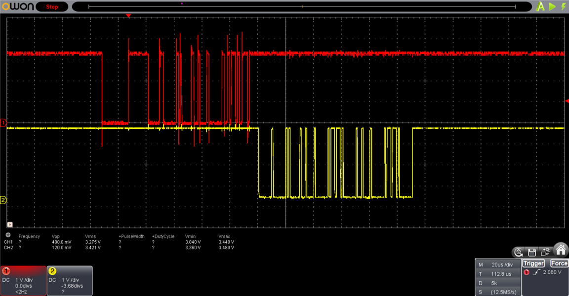
    I will attach a couple of images. Submit a read of the "DEVADD_USR" register.

    The UART is configured with a start bit, a stop bit, 8 data bits, no parity and is FIFO.
    In red the query and in yellow the answer of the BQ79606. In this case the query went to the bridge. To understand a bit how I send the data, I will put part of the code below:

    /******************************************************************************************************/

    #define BMS_BRIDGE_ADDRESS 0x00
    #define BMS_REG_DEVADD_USR 0x0104
    #define FRAME_INIT_SIGLE_DEVICE_READ 0x80

    uint8_t rx_data[7];


    bool BMSCheckBridgeAddress() {
    BMSSingleDeviceRead(BMS_BRIDGE_ADDRESS, BMS_REG_DEVADD_USR, 1);

    BMSReciveData(BMS_BRIDGE_ADDRESS, BMS_REG_DEVADD_USR, rx_data, 1);
    }

    bool BMSSingleDeviceRead(uint8_t dev_address, uint16_t reg_address, uint8_t n_data) {

    bool error = false;
    uint16_t crc;

    if ((dev_address < 0x64) && (n_data <= 128) && (n_data > 0) && (!error)) { /*Check n_data and device address */

    UART2TxMsgBuf[0] = FRAME_INIT_SIGLE_DEVICE_READ;
    UART2TxMsgBuf[1] = dev_address;
    UART2TxMsgBuf[2] = (uint8_t) (reg_address >> 8) & 0xFF;
    UART2TxMsgBuf[3] = (uint8_t) reg_address & 0xFF;
    UART2TxMsgBuf[4] = n_data - 1;
    crc = BMSCalculateCRC(UART2TxMsgBuf, 5 * BYTE);
    UART2TxMsgBuf[5] = (uint8_t) (crc >> 8) & 0xFF;
    UART2TxMsgBuf[6] = (uint8_t) crc & 0xFF;

    UART2TxSetNdata(7);
    tx_timeout = 0;
    UART2_WriteBuffer(UART2TxMsgBuf);
    }
    else{
    error = true;
    }
    return error;
    }

    uint16_t BMSCalculateCRC(const uint8_t *data, uint8_t n_data) {
    uint8_t aux;
    uint16_t CRC = 0xFFFF;
    while (n_data--) {
    aux = *data++ ^ CRC;
    CRC >>= 8;
    CRC ^= CRC_table[aux];
    }
    return (CRC << 8) | (CRC >> 8);
    }

    void UART2TxSetNdata(uint8_t n_data) {

    UART2_buffer_length_tx = n_data;
    }

    uint16_t UART2_WriteBuffer(uint8_t *buffer){
    uint16_t numBytesWritten = 0;
    uint16_t counter = 0;

    if(U2STAbits.UTXEN == 0){
    U2STAbits.UTXEN = 1;
    }

    while (numBytesWritten < (UART2_buffer_length_tx)) {
    UART2_Write(buffer[numBytesWritten]);
    numBytesWritten++;
    }
    return numBytesWritten;
    }

    void UART2_Write(const uint8_t byte) {
    U2TXREG = byte; //Load the byte in the Tx register
    while (!U2STAbits.TRMT);
    }

    /******************************************************************************************************/

  • Hi Saverio,

    Thank you for sharing the additional information. I'll review this and have some feedback by the end of the week. 

    Can you also clarify what device you are using as the bridge device? 

    Best Regards,

  • The bridge is also a BQ79606. The interesting thing is that it always answers what I ask, so the communication works, but I have to limit the characters that I read from the buffer to a size that I must know in advance.

  • Hi Saverio,

    Thank you for the clarification. I'll review all the information you provided and share some feedback tomorrow.

    Best Regards,

  • Hi Saverio,

    Can you clarify if you are working with the BQ79606EVM or with custom hardware? If you are using custom hardware, can you check the BQ79606 example code with your hardware? This would help verify that you do not have any hardware issues before we dig deep into debugging code.

    You can find the example code here: 

    Best Regards,

  • Good afternoon,

    I've been making a lot of changes to the firmware I use. I don't have the BQ79606EVM board, all the hardware was developed by us, but based on that development board. The example they gave me helped me to analyze the firmware a bit. After many changes in the programming I managed to stop seeing those extra bytes but I don't know why they appeared ...
    I did not answer before because I was trying to find what my mistake was, but I already solved it, thanks !.

    Hardware Development

    Saverio Carnevale

  • Hi Saverio,

    Glad to hear you solved your issue! Let us know if you have any other questions.

    Best Regards,