This thread has been locked.

If you have a related question, please click the "Ask a related question" button in the top right corner. The newly created question will be automatically linked to this question.

Need Li-Ion Battery Charger IC/circuit

Other Parts Discussed in Thread: BQ24610, LM61460, TPS560200, BQ24610EVM, LMR14050

Hi,

We are designing the product for Medical Application, So all the Components should be Medical grade/standard under required IPC standard and it should be approved for all the certifications required for Medical applications. So, Kindly suggest accordingly.

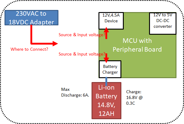
Our Device Working Voltage is 12VDC, 4.5A.

Battery is 14.8V, 12AH Li-Ion Battery( to backup for 2hours), Charging Voltage/Current: Standard (16.8V @ 0.3C suggested by battery manufacturer)

AC to DC Adapter: 18VDC,5A or you can Suggest right one.

FYI: Our Device working with 12VDC, 4.5A while operation and 0.2A when No-Operation, AC to DC Adapter and Battery is always be connected to the device. If power fails, the device will power up from battery automatically without any restart/delay/Glitch and if power resumes device will power up with adapter and the Battery will charge through the Charger circuit. Switching function will not cause to any Restart/Glitch of the device.

Device should have Onboard DC-DC converter 12VDC to 3.3VDC.

1. Please find the attached image, We are having 18V source, 14.8V Battery, 12V device. How we can interface Charger and DC-DC circuit between these 3. Kindly Advise.

2. Kindly Suggest the Power Tree for the Above scenario (From 18VDC(Adapter) to 12VDC,3.3VDC)

3. Kindly Suggest the Charger IC, DC-DC Regulator along with the circuit and rough Block Diagram for understanding.

4. I have to monitor Battery voltage level and Adapter status(Device Supply from Battery or Adapter), We can monitor through ADC by measuring voltage on Battery +pin & Adapter +pin, if charger doesn’t have this feature.

 Kindly help us to build efficient Product.

Thanks and Regards,

Naveen k

  • Hi Naveen,

    There is a lot here, let me try to suggest the best parts for each section:

    1. For the battery charger - BQ24610 should work

    2. 18V to 12V / 4.5A - LM61460 will work well

    3. 12V to 3.3V / ?A - I assume the current is fairly low here, TPS560200 will support up to 500mA

    Hopefully this helps.

    Thanks,

    Robert

  • Hi Robert,

    Thank you for the information.

    We need Li-Ion Battery Charger for the following Battery specification.
    Cells: 4-Series-4-Parallel
    Battery Voltage: 14.8V
    Charging Voltage: 16.8V
    Charging Current: 3A and 2.5A (we are having two models)
    Discharge Current: 5A
    Adapter output: 18V 19V or 24V(depends on standard/availability)

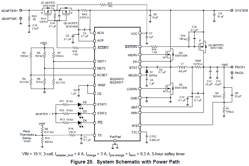
    We gone through the datasheet, we are having few queries on BQ24610 schematic as attached, Kindly help us.

    1. Can we supply both 18VDC or 19VDC or 24VDC from the adapter without changing any component/value in the schematic right?
    Schematic is independent to the adapter voltage and Current if voltage 2V higher than "Batter Voltage". right?
    2. In "11 Power Supply Recommendations" mentioned input voltage at least 1.5 to 2V higher than the Battery Voltage. Here, Battery Voltage mean, Battery Charging Voltage(16.8V) or Only Battery Voltage(14.8V)?
    3. To change Battery Charging Voltage(in schematic its 12.6V) to 16.8V, What will be the R1 & R2 Value? any other component/value to be change?
    4. If Charging current is 3A, we will use same component/value in the schematic. If the Charging Current should be 2.5A, What will be the changes we have to do?
    5. RSR resistor and L1 value remains same for both battery charging current 3A and 2.5A? or need to change the value? or R5,R6,R7,R8 value to be change, kindly advise.
    6. To Change the Adapter output(Supply IN) voltage(18V or 19V or 24V) and Current(5A or 7A), RAC resistor or any other component value remains same or need to change the value? R3, R4 value has to be change? kindly advise.

    7. If thermistor not present in the Battery Pack, Can we Uconnect or float the TS pin?


    Thanks and Regards,
    Naveen K

  • Hi Naveen,

       All these questions are answered in the datasheet. Please refer to the BQ24610 datasheet: 

    1. Yes. Make sure your passive components are rated accordingly, taking into derating of ceramic capacitors with applied voltage.
    2. It means measured battery voltage, but you will need to take into account the worst case SLEEP condition and design based off of the max charge regulation voltage
    3. Datasheet
    4. Datasheet
    5. Change ISET1 voltage based off of the formula shown in the datasheet
    6. Discharge current is not a setting, and is based off of your load requirement
    7. Refer to TS section of the EC table of the datasheet. Fix TS voltage in the recommended range.

  • Hi Kedar Manishankar,


    Thank you for the information.

    We gone through the datasheet and understood that only ISET1,ISET2,ACSET,VFB (Resistor Network value) should be change with respect to Battery Charging Current, Precharge/Termination, Adapter Current, Battery Charge Voltage. Other part/component/values remains same irrespective of Charge Voltage, Current, etc.

    1. For set the Charging Voltage to 16.8V; R1=100KΩ and R2=700KΩ.
    2. For set the Charging Current to 2.5A; R7=100KΩ and R8=17.857KΩ.
    3. For set the AC adapter current limit to 5A; R3=100KΩ and R4=43.478KΩ.
    4. We know how to set ISET2. But, Kindly advise, What will be the I_precharge and I_Termination current for our 14.8V,10Ah Battery? Precharge and Termination current value should be equal?
    5. If TTC pin connected to capacitor as in the schematic, which enables the Termination and Safety timer right?
    6. In section 9.3.6/9.3.14 mentioned “VCC can be supplied either from the battery or the adapter” If No-Adapter, How the Charger_IC VCC powered from Battery? Because in schematic there is physical connection from battery to VCC.
    7. When the IC will go to Sleep Mode? During sleep mode Charging will Happens? During Sleep mode adapter can able to power to the load? How/when device will come back from sleep mode?
    8. Regarding to section 10.2.1.2.5 Input Filter Design, the circuit is already present in the schematic right?


    Thanks and regards,

    Naveen K

  • Hi Naveen,

       In this part, the precharge and termination current are set by the same ISET2 pin, so whatever threshold you set for VISET2 will be applicable for both. Generally 10% of fast charge current is used for precharge current and termination current, but ISET2 gives you the configurability. If there is no adapter then there is a path to VCC from battery through the body diode of the HSFET, but this doesn't matter as the SLEEP (as VSRN>VCC) threshold would be triggered and converter would not be active, and would be in a low quiescent current mode. There is a specification in the datasheet for entering and exiting SLEEP as there is hysteresis built in.

    For actual calculations, if you have used the correct formulas from datasheet then you will be fine. As an added help we also provide this calculator tool: www.ti.com/.../sluc175

  • Hi Kedar Manishankar,

    Thank you for the information.

    1. Comparing between Application Schematic(Figure 20) in the BQ24610 datasheet and BQ24610EVM Evaluation Schematic (Figur.10 considering only Application Block, other block not required), There is a additional components (Resistor, Capacitor, Diodes) present on Evaluation schematic compare to BQ24610 datasheet. Kindly suggest which Schematic we can consider for our application.

    2. What will be the power consumption of the Charger IC and 19VDC-12VDC regulator(LM61460), 12VDC to 3.3VDC regulator(TPS560200)? because, we are estimating the power consumption of each block to select the battery capacity. Our all 12V & 3.3V Block will consumes 4.5A (we are considered Absolute max current consumption of the part which is mentioned in the datasheets). Unable to find for Charger IC/Regulator, kindly help us.

    3. We can refer any MOSFET/Diode part number in Datasheet or EVM board, both are giving efficient results right?

    4. Once we done the PCB layout design for the Charger Circuit, could you review?

    Thanks and regards,

    Naveen K

  • Hi Naveen,

    1.  I would use EVM as a starting point for your schematic
    2. Regarding the other regulators, please create separate posts with those part numbers in the title/tag and the expert supporting those parts can answer your question. I am not familiar with those portfolios
    3. I would use EVM as a starting point, but datasheet also describes the features you want to consider when selecting external components. EVM was designed a while back, so there are more likely better/more efficient options available in the market today. Refer to section 10.2.1.2 Detailed Design Procedure of the datasheet

  • Hi Kedar Manishankar,

    Thank you for the information.

    1. Could you please suggest the MOSFET package, because MOSFET should not be heatup. How i can select the right MOSFET to avoid heating?

    2. Our requirement is Adapter Voltage=19VDC, Battery: 4cell-series,3cell-parallel, 16.8V, 9Ah, Charging/Discharge current: 2.5A to 4A. BQ24610 may high hand version, having more number of components. So could you suggest any other IC which having simple circuit with cost effective, but similar efficiency.

    3. We have considering LMR14050 instead of LM61460 you have suggested. We can use LMR14050 (SO-8 package) right? it will work efficiently, without heating up right? LMR14050 is right selection for our requirement/application?

    Thanks and Regards,

    Naveen K

  • Hi Naveen,

      Regarding the battery charger, this is the best recommendation for you system considerations. If you wish to look at the rest of the portfolio, you can do so here:

    For the other parts, I would recommend creating separate posts with those specific parts in the title. The experts supporting those parts will be able to answer your questions.

  • Hi Kedar Manishankar,

    Thank you for the information and appreciate your support.

    It was great helpful for us.

    Thanks and regards,

    Naveen K