This thread has been locked.

If you have a related question, please click the "Ask a related question" button in the top right corner. The newly created question will be automatically linked to this question.

TPS27S100: Problem for Vout float up and question about open load detection

Guru 19645 points
Part Number: TPS27S100

Datasheet page 19~20 are described about open load detection and external 15kΩ pullup. 

When no load condition (although connecting LED for small supply current) and add 15kΩ pullup to IN~OUT, Vout is float up to 4V on EN: OFF status.

Removed 15kΩ pullup condition was not Vout float up (0V).

Please let me know about the reason of Vout float up and measure.

When possibility to reach no load condition, is pullup require to connect, correct? 

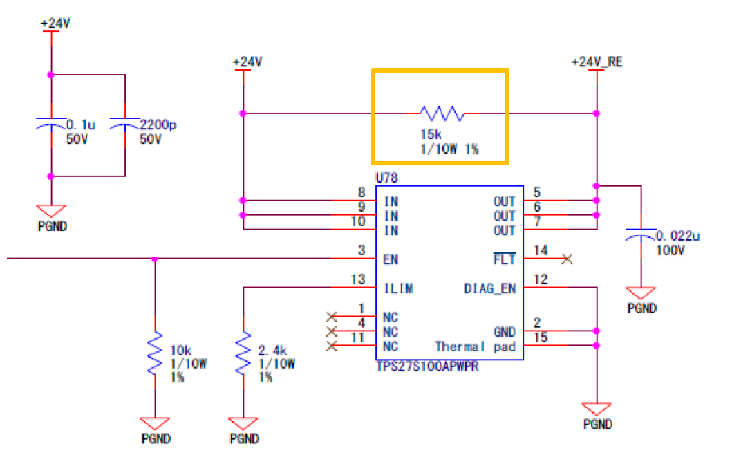
External component is below;

Parts #: TPS27S100APWR

Vin and Vout: 24V 

Cin: 100nF and 2200pF 

Cout: 22nF

EN: external input with 10kΩ pulldown

ILIM: 1A and 4A (two case)

DIAG_EN: GND (Unused)

/FLT: NC (Unused)

IN~OUT: 15kΩ Pullup

※Power ON/OFF Waveform is attached below, ch1: EN and ch2: Vout

Best regards,

Satoshi

  • Hi Satoshi-san,

    For open load detection in the off state, there is always a reference current sinking into the ON pin defined as I_ol,off. The 15Kohm pull up allows the I_ol,off to be provided from VBAT but the drain to source voltage drop across this is still less than V_ol,off which triggers the open load fault.

    Can you please share a schematic? And what do you mean by "although connecting LED for small supply current". If there is truly no load, then the output should float up to the input voltage. 

    The waveforms that you attached seemed to show that in normal operation, the device works fine.

  • Hi Shreyas

    Thank you for reply,

    I attached schematic. (+24V_RE is Vout)

    About the mean of LED, Vout side is connecting LED for Vout detection (= nearly no load), but before long LED will remove.

    Attached waveform is Vout floating up 4V on EN: Low state.

    Our hope is Vout: 0V on EN: Low state, is there way to adjustment?

    Best regards,

    Satoshi

  • Hi Satoshi-san,

    Thank you for sharing the schematic.

    The waveform that you are referring to is not attached here. I think the LED is indeed providing some load since I expect the output waveform to rise up to 24V instead of 4V. This floating node is powered by the I_ol,off which is only 50uA so any load on the output could be enough to pull this down. This is how the device is configured where in an open load condition the output will float to the input which triggers the open load detection.

    If you would prefer that the Vout is 0V then the device must be tricked into thinking there is never an open load. I think you will be forced to use some sort of output pull down resistance like a 10kOhm path to GND on the output rail. I also believe the 15kOhm resistor can be removed.

    In this state the open load detection from the device will not work but you can build some external circuitry (like you already did with the LED) that provides feedback to the user. Would this be acceptable?