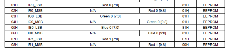
On the X-axis in Figure 7, the current setting looks like 9 bits up to 1023, while the LED current setting registers from 01h to 12h have a 10-bit (8-bit and 2-bit) allocation.
Does the D1 bit of the even address (02h, etc.), which is the MSB, affect the LED current?
Also, I cannot understand the relationship between the Y-axis output current in Fig. 7 (maximum 720mA) and the Y-axis in Fig. 13 and Fig. 14 (red is maximum 600mA, green is maximum 500mA, blue is maximum 400mA).
On the LM3549 evaluation board, when the registers are set as shown below, the LED DC current of each R/G/B channel seems to be 400mA.
Addr Value
00h 00h using Bank0
01h FFh IR0 LSM
02h 01h or 11h IR0 MSB
03h FFh IG0 LSM
04h 01h or 11h IG0 MSB
05h FFh IB0 LSM
06h 01h or 11h IB0 MSB
14h 00h No brightness control
I don't know how to set the DC current of the R_OUT pin to 600mA.

-
Ask a related question
What is a related question?A related question is a question created from another question. When the related question is created, it will be automatically linked to the original question.