This thread has been locked.

If you have a related question, please click the "Ask a related question" button in the top right corner. The newly created question will be automatically linked to this question.

LM5064: There is a reset issue affecting separate units.

Part Number: LM5064

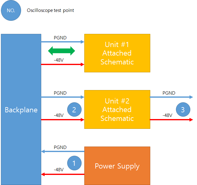
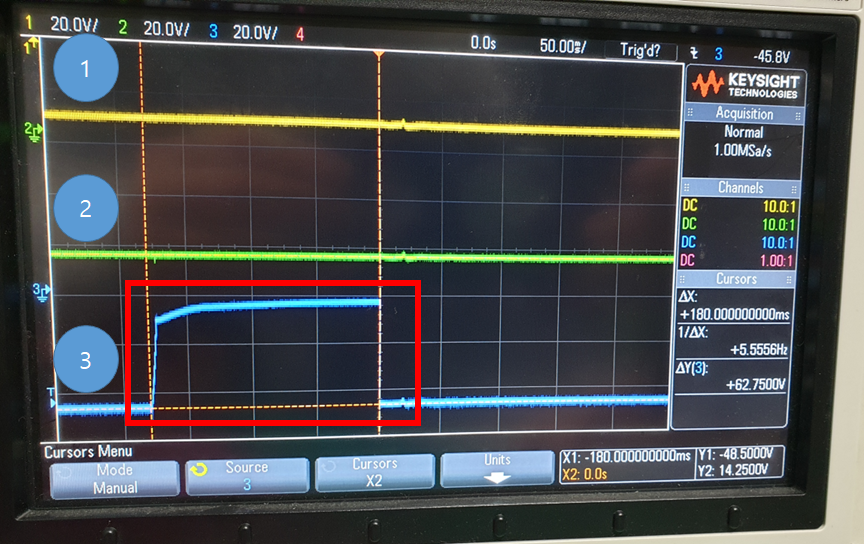
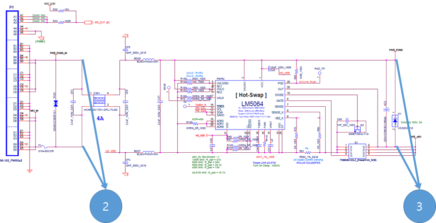
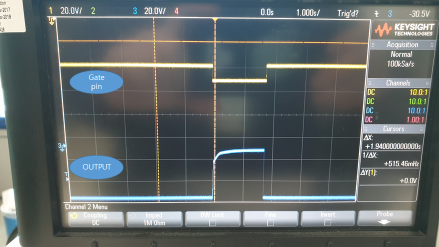
The system is configured as shown in the attached picture. If Unit #1 is inserted while Unit #2 is inserted, it seems that Unit #2's hot-swap (LM5064) is in progress. -Oscilloscope point 3 (actually reset.)
When the power supply and the input power of Unit #2 are checked by scope, there seems to be no problem at all. I have no idea for any reason.
The above phenomenon is also the same in the opposite case.
(For example, when Unit #1 is inserted while Unit #2 is inserted)

  • Hi Park,

    Use a filter cap across the shunt resistor similar to Figure-11 in https://www.ti.com/lit/an/slva703/slva703.pdf and check.

    Can you probe GATE and timer also on Unit#2 to check whether the device is resetting

    Best Regards, Rakesh

  • As shown in the attached schematic below, Use and check a filter cap on a shunt resistor. I tried changing the 1nf, 100pf, and 10pf, but the result was the same.

    With an oscilloscope, I measured the gate pin and the external FET output stage. It was confirmed that the LM5064 blocks the output of the gate pin.
    I wanted to measure the timer pin, but when I connect the probe to the timer pin, the power turns off. How do I measure it?

    To further check, I read BLACK_BOX_READ (E0h). However, no special faults appeared.

  • What are the values of R69 and R70 ? If it is 0 Ohms, please retest with 10 Ohm value and 100nF for C47

  • R69 and R70 value is 0 Ohms. As advised, I retested with 10 Ohm value and 100nF for C47.

    However, the results were the same.


    I chose the LM5064 because hotswap and power monitoring were needed, but I wonder if the LM5064 cannot be used in the current situation. What is the problem.

  • Incidentally, when the timer capacitor C44 is lowered at 220nF, the phenomenon does not appear.
    Here are some questions.
    1. Why did this result appear according to the Timer CAP?
    2. I want to know why the gate is not turned ON depending on the capacitor value (less than 220nF).
    ex) 1nF is ON, 10nF is OFF, 20nF is ON
    3. If the reboot is repeated, a situation occurs where the gate is not turned on. There is no problem with the input power, but the retry does not proceed and the gate is kept closed. The retry pin is connected to VEE.

  • Hi Park,

    1A, 2A) Can you share test waveforms for each of the case. Measure input current, timer cap voltage, drain of the MOSFET, GATE nodes with respect to VEE of the device.

    3A) Is it timing out due to reduced timer capacitor value ? Please check input current, timer cap voltage, drain of the MOSFET, GATE nodes with respect to VEE during powerup.

    Best Regards, Rakesh