This thread has been locked.

If you have a related question, please click the "Ask a related question" button in the top right corner. The newly created question will be automatically linked to this question.

TPS1H000-Q1: No fault diagnostics on overheat

Part Number: TPS1H000-Q1
Other Parts Discussed in Thread: TPS1H000EVM,

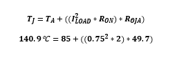
I'm using the tps1h000 in hold mode with current limit set to 850mA

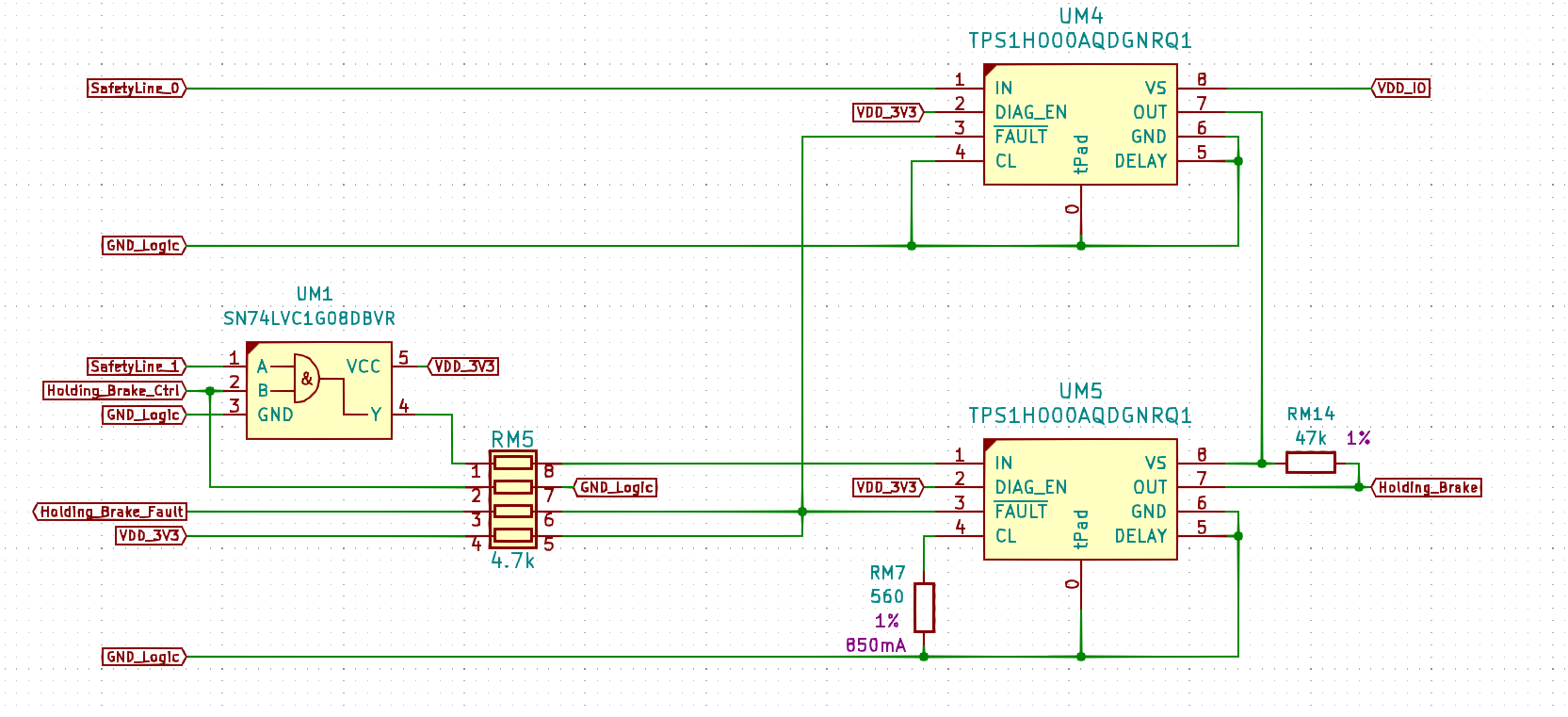
Please ignore the additional fluff in the schematic. For all intents and purposes, I'm describing a situation where both UM4 and UM5 have 3.3V on their inputs.  When I load the output (Holding_Brake) to approx 750mA, the chips heat up and in about 30-40 seconds one of them begins cutting out it's output temporarily. This is all just fine and I will address it by switching to tps1h200 and providing more copper. The issue that I'm seeing however is that when the chip begins to cycle it's output off, the fault pin does not pull low, so the MCU doesn't know about the issue.

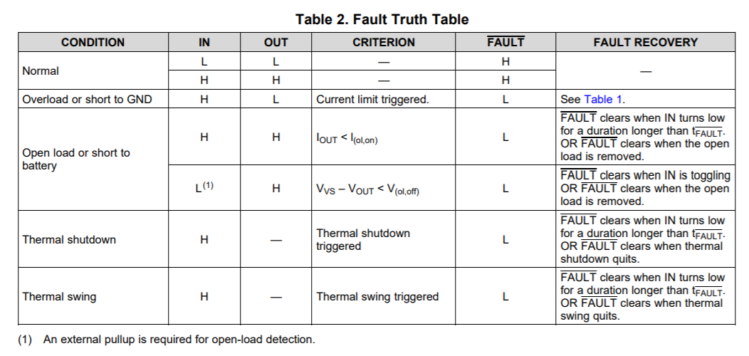
The datasheet ( on page 15 and 16 ) clearly shows that a thermal shutdown should activate the fault pin, but I can't get it to do so. The timing diagram on page 16 shows the output toggling on/off and I've confirmed that it does, but the fault pin never goes low. If I overload the output, the current gets clamped and the fault pin pulls low. If I have no load, the condition gets detected and the fault pin goes low. So I can confirm the fault pin operation and the MCU reading it properly.

Just to make this clear, in my problem scenario, the load never reaches the limit set by the CL pin and I believe the chip overheats due to it's 1-ish ohm resistance. Is it possible that if the chip overheats while NOT in current limit, the FAULT pin doesn't pull low?

Thanks in advance

  • Hello Ermil,

    The device is rated to 1 A, at 750 mA you should not be going into thermal shutdown. Could you provide more information? What ambient temperature are you operating at? Unless there's a problem with the layout, you should not be hitting thermal shutdown. Could you also provide a scope shot to ensure that the FAULT pin does not go low during the event?

    Regards,

    Kalin Burnside

  • Hi Kalin,

    Here's some oscilloscope traces. Purple is current, Yellow is the FAULT signal. Ambient is 23C, but keep in mind, the chip has no proper cooling at all.

    1 - Start. Everything is cool, this is a trace right after activating UM5. Fault is high as expected.

    The current measurement from the current probe is a bit noisy, but I've verified that it is reading properly at 750-800mA. As the chip warms up, I can see the current slowly decrease by maybe 50mA which is consistent with the increasing of the on resistance.

    2 - After the chip is ON for approximately 30-45 seconds, I get the following:

    As you can see, the output begins to cycle on/off, but the FAULT signal remains high. At this point the plastic case of the chip measures 90-100 C and I think it is actually higher because I don't have very good contact while holding my thermo-couple pressed against the chip itself.  I believe we have not put enough copper for that chip to dissipate it's heat and I think it goes into thermal shutdown or thermal swing protection, but why is the FAULT not pulled low? In our next iteration we will address the issue of cooling and we will change the chip to the 200mOhm version, but I need to understand this weirdness about the fault signal because it appears to contradict the datasheet.

    3 - Just as a proof that the fault signal works in other scenarios, here's a trace of trying to draw 12A from the output:

    As expected, the output toggles and the FAULT signal is low, so the signal and wiring is fine.

    Any insight is greatly appreciated,

    Thanks.

  • Ermil,

    One thing I do not understand here is how the device would be reaching thermal shutdown at 23C ambient temperature and a 750mA load current. This device is designed to be able to support a nominal steady state DC load current of 1A at 85C. What does your soldering layout look like? Is there no solder coverage on the thermal pad?

  • The thermal pad is soldered and it goes to a ground plane that is on the inner layers so I don't believe it helps much. It has some thermal mass, but cannot dissipate through the FR4. There's also 2 chips in series in extremely close proximity, so that center ground plane I'm sure gets saturated with heat pretty quick.

    Guys, worst case power dissipation is 0.8A^2 * 2ohm = 1.28W, so top of the case to junction should be 1.28 * 50.2 = 64.3 degrees Celsius and if I'm measuring 90+ on the top of the case, then junction is at least 150C

    Let me say this again, I'm reworking the design to provide for better cooling, that's fine. I need to understand why the chip cuts its output out without pulling the FAULT signal.

    I even tried turning on another output that uses the same chip and using hot air, got it's case temperature to above 150C. The Fault didn't pull low. Are you sure the fault signal will activate if the chip is not in current limit? The datasheet surely suggests that it should. Am I missing something? Anything else I can check that might explain seeing a solid 0.8A for 30-40 seconds that all of a sudden begins toggling?

    I'm not trying to be difficult, but my design decisions depend on how the chip functions and I just need to understand the details and as an engineer, the datasheet is my bible.

    Thanks a lot for taking your time to look into this.

  • Ermil,

    If the device hits a thermal shutdown or thermal swing the FAULT pin should be driven low regardless if the current limit has been tripped or not. This is documented in the datasheet in the fault table:

    I have scheduled some lab time tomorrow to put the TPS1H000EVM in a thermal stream with your applications specific loading conditions to reproduce this. I will post the results after the testing has been completed.

    To understand your design a little better would you be able to answer the following questions?

    • What is your supply voltage being fed into VS?
    • What is the purpose of daisy chaining the output of one TPS1H000-Q1 to the input of the other? This is generally not recommended as if there is a fault on the first device the second device becomes unpowered (and the state of the pins are unreliable)
    • What is being placed on the load? Are you controlling via an electronic load or are you using physical components to achieve the various test load currents?

  • Timothy and Kalin,

    I found the issue. It turns out UM4 had a bad solder joint on the fault pin. UM4 was the one that was overheating first ( pretty much by chance ) and was cutting out the current. UM5 never actually faulted and the CPU ( and me measuring the trace) only saw UM5's fault signal. Once I fixed the solder joint on UM4's fault pin, everything started working as per the datasheet.

    Just FYI, I'm powering the circuit with 24V and using resistors as load. I try not to use my electronic load unless I have to because it sometimes cases weird high speed load variations. The reason we daisy-chained two chips is to have hardware redundancy for this part of the circuit. This is a requirement from a safety standard that we need to pass. If any of the two control signals are off, we have a very high probability of the load being off even if part of the circuit has failed. I can deal with the temporary uncertainty of UM5 being powered down in software and ignore the fault signal if it turns out to be needed.

    Thank you very much for your efforts and I apologize for sending you on that wild goose chase. In the end, the chip works as expected and all we have to do is provide it with proper heat dissipation.