This thread has been locked.

If you have a related question, please click the "Ask a related question" button in the top right corner. The newly created question will be automatically linked to this question.

BQ76930: BQ76930 cascade 20 series short test

Part Number: BQ76930

Hi

The customer use two BQ76930 cascades to design 20 series of iron-lithium protection boards.

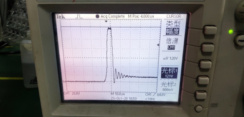
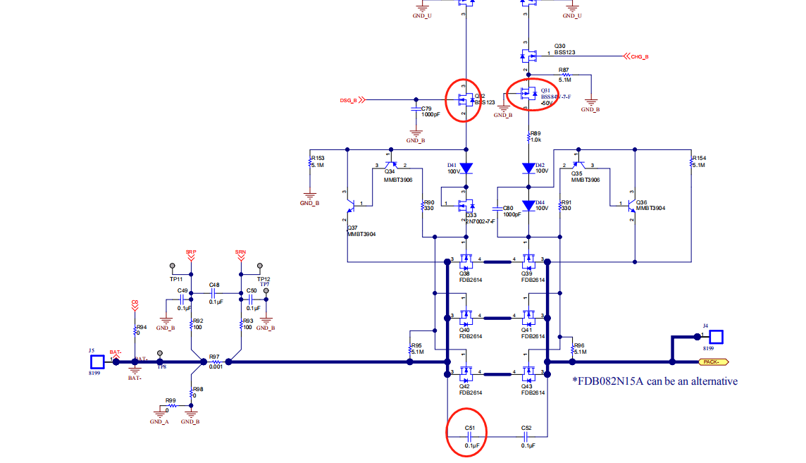
During the short circuit test, it is found that there is an instantaneous high voltage between the DMOS, the voltage is about 120V, and delay time is 7.2uS, the capacitor C37 (marked) damage and other components, as shown in the figure.

(Trying to add a 90V TVS tube between B+/B- and adding a Schottky diode between B-/P- is invalid)

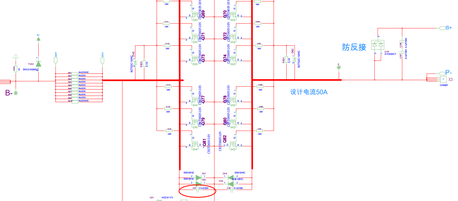
The attached figure mark the component is easy to damage. the failure rate about 0.5~1%

Please give some suggestions.

 Thank you

Star

  • Hi Star,

    I am not too familiar with this circuit. Let me check with the person who created this reference design and get back to you.

    Best regards,

    Matt

  • Hi Star,

    In the TI schematic, C51 and C52 are a pair connect in series. In the customer schematic they are connecting the caps in the center. If they follow the TI schematic, it will allow the voltage to divide across the two caps, so 120V should only give 60V on each.

    In the TI schematic, R90 is used to slow down the switching. This might be helpful.

    We are not sure how Q31 and Q32 are damaged. It may be necessary to capture this on a scope to see what is happening. Is the D42 diode rated higher than 100V?

    Best regards,

    Matt

  • Hi Matt

    Thanks for your reply.

    From test we found that if the capacitors at both ends of the MOS are removed or the TI reference design is used, there is no instantaneous pulse. 

    what is the purpose of connecting the capacitors in parallel between P-/B-? What are the risks of removing these two capacitors?

    Thanks

    Star

  • Hi Star,

    These two series capacitors are for ESD protection. With 2 in series, if one fails (shorts), the other will still be present to provide protection.

    This document has a good discussion on using capacitors across the FETs for ESD protection (see Section 3): https://www.ti.com/lit/an/slua368/slua368.pdf 

    Best regards,

    Matt