This thread has been locked.

If you have a related question, please click the "Ask a related question" button in the top right corner. The newly created question will be automatically linked to this question.

UCC28740-Q1: Shutting down continuously

Part Number: UCC28740-Q1
Other Parts Discussed in Thread: TIDA-010000, , UCC28740

Hi There,

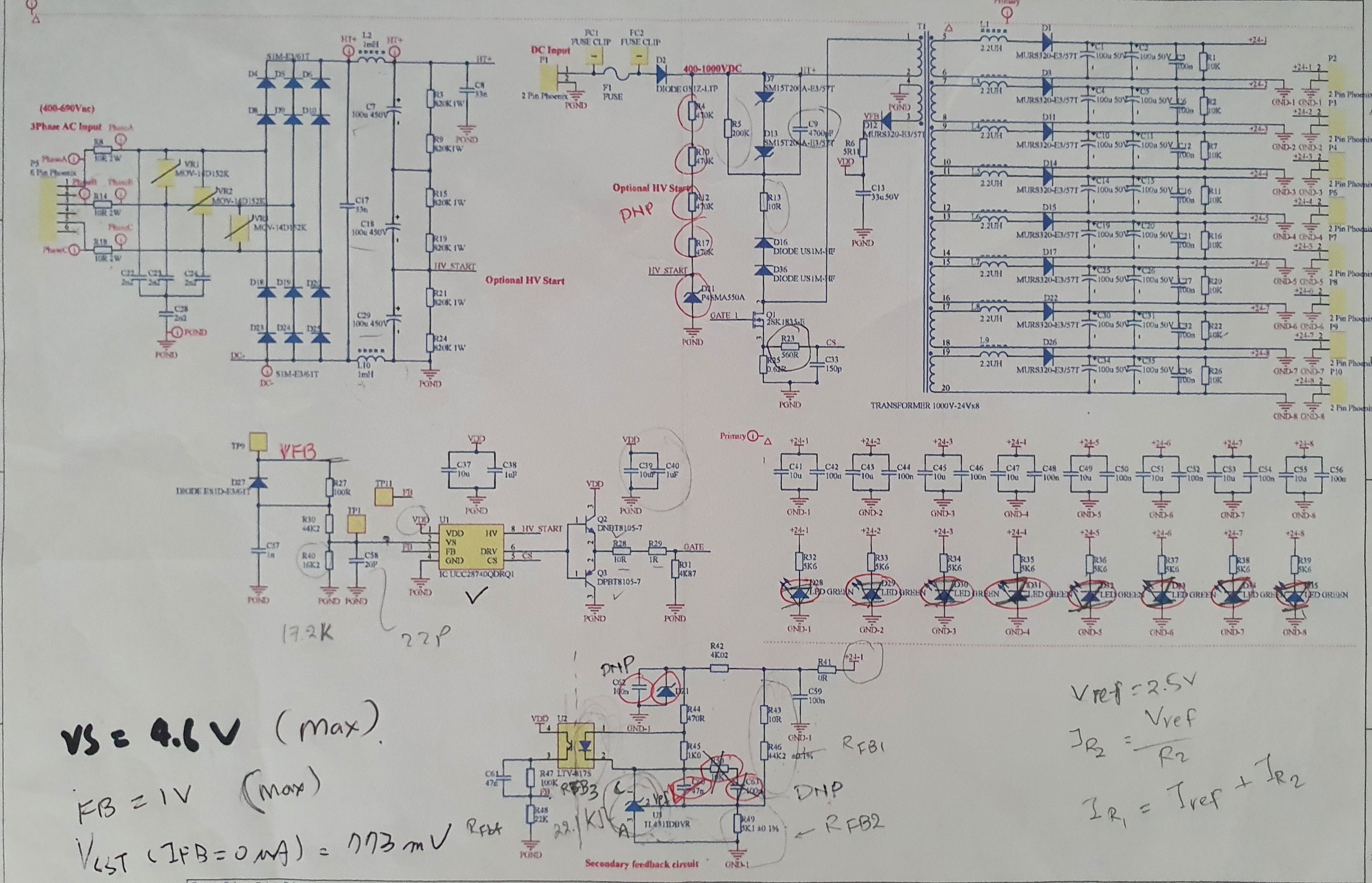
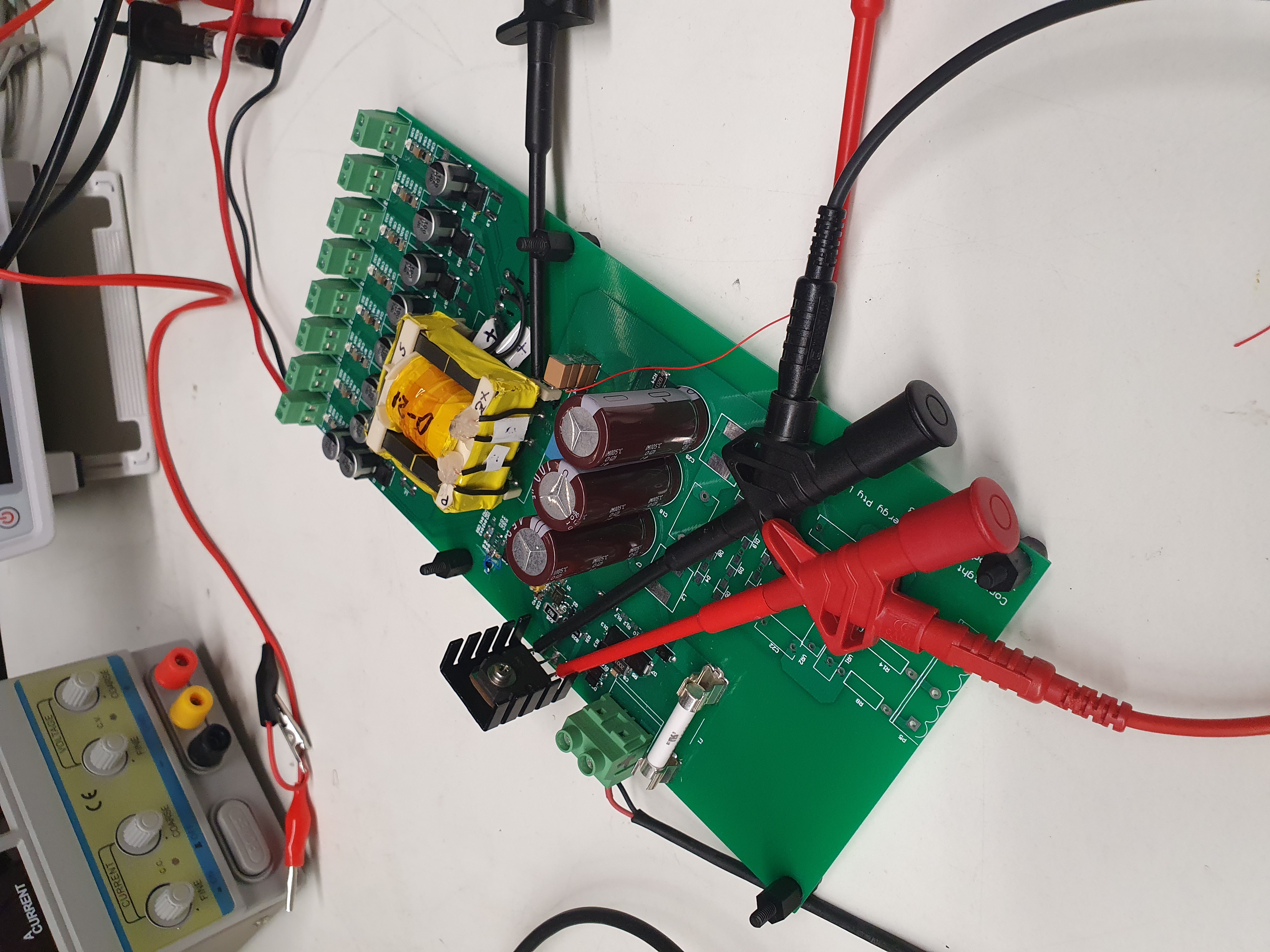
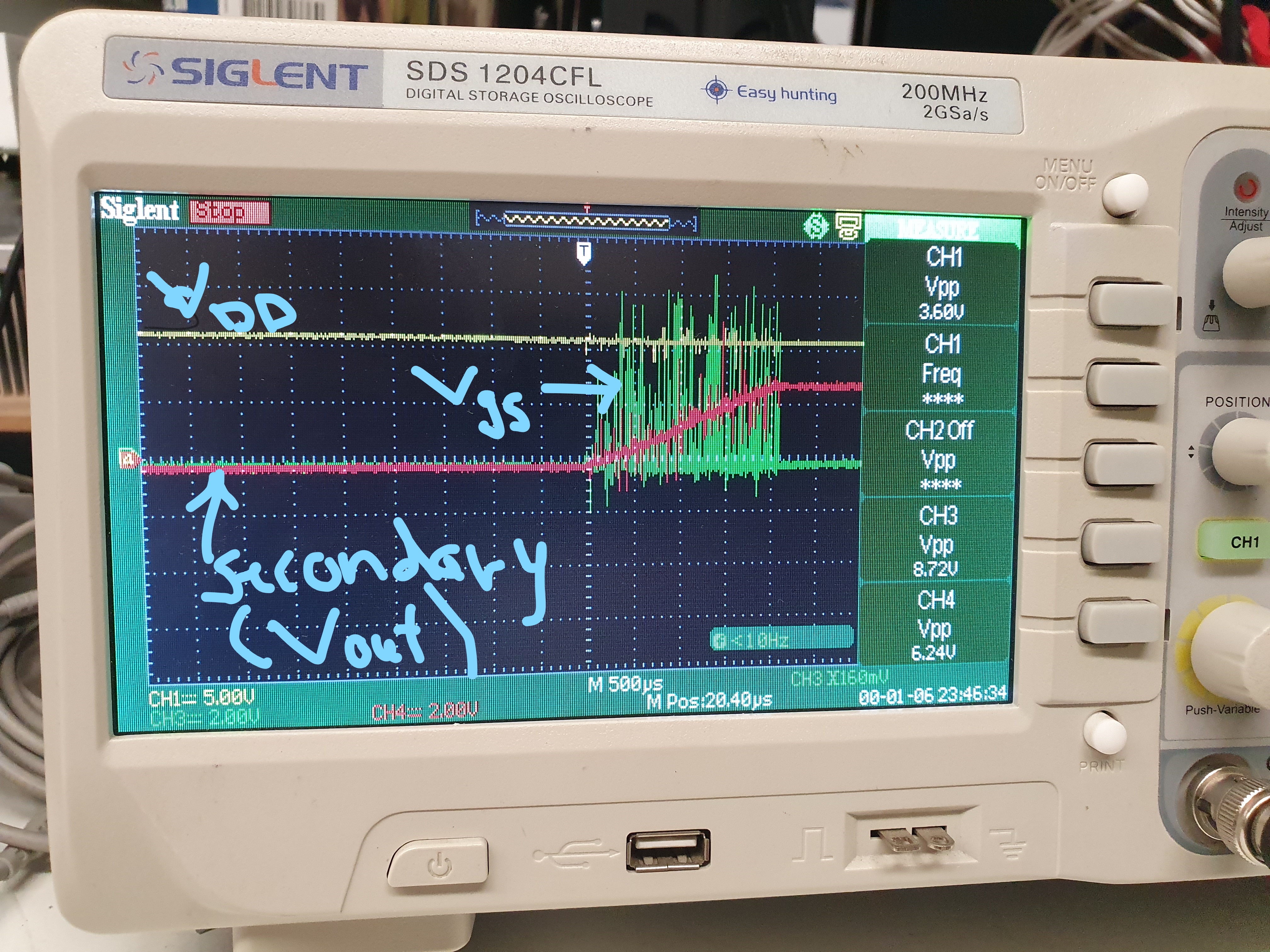
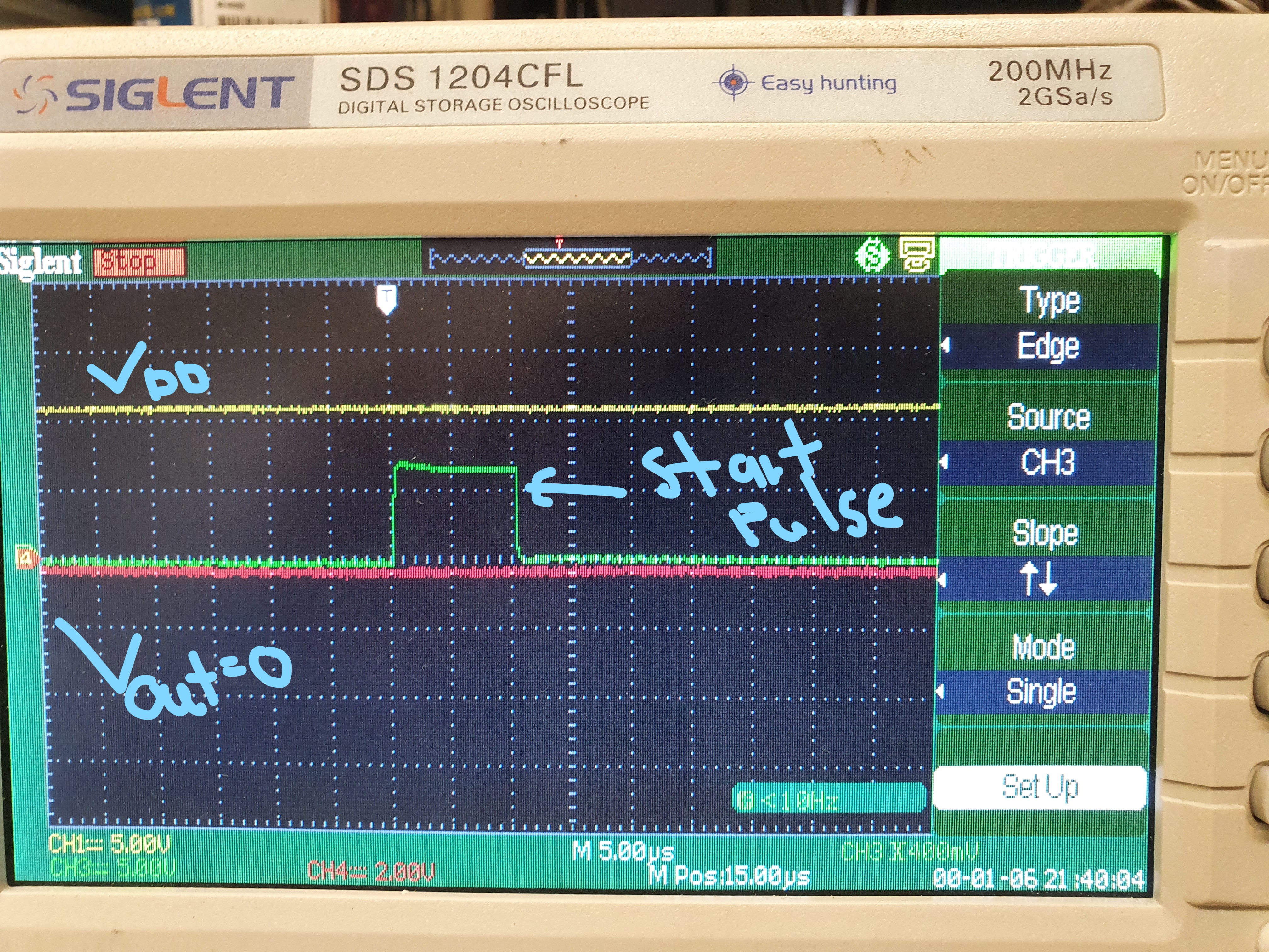
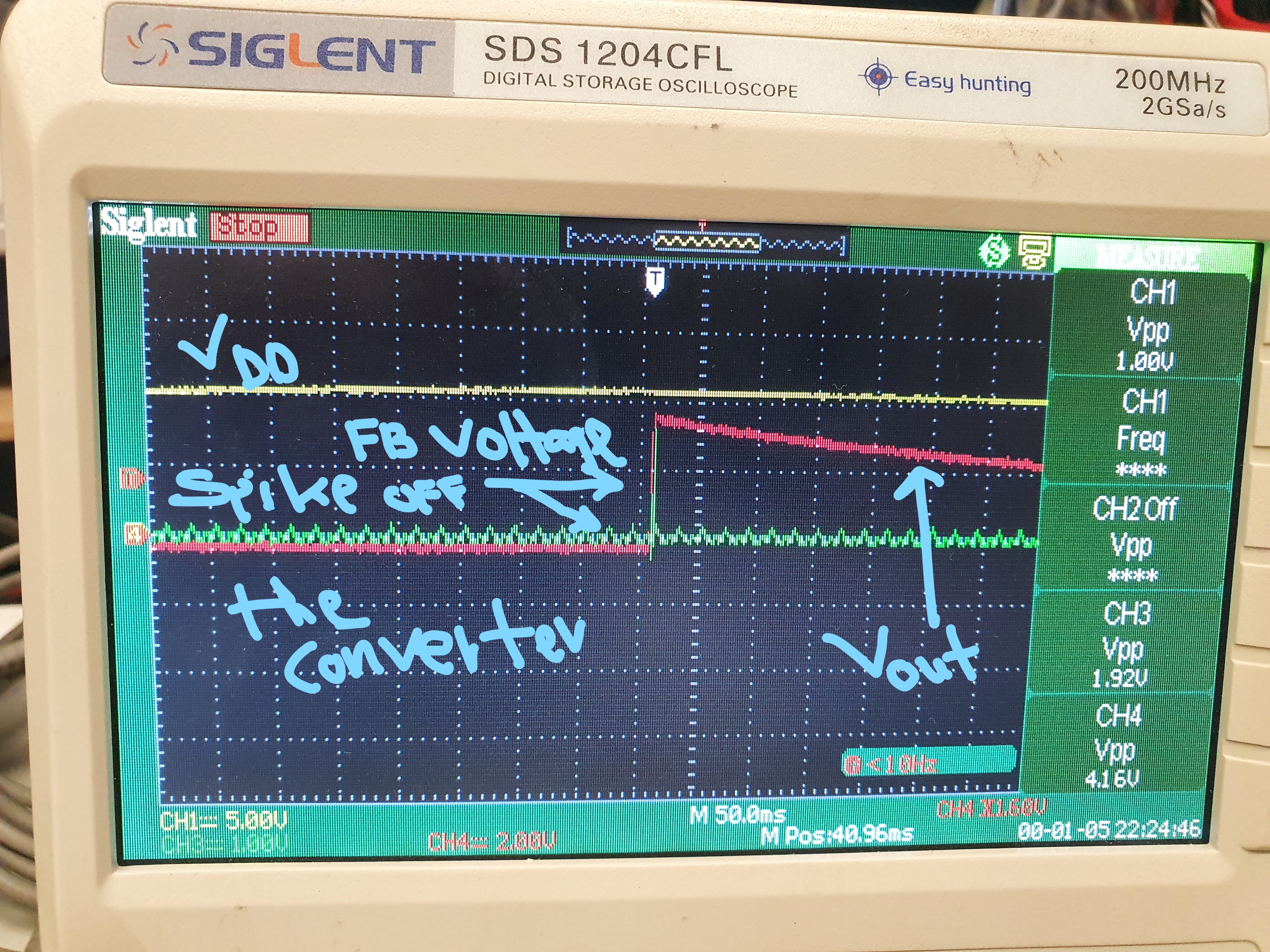
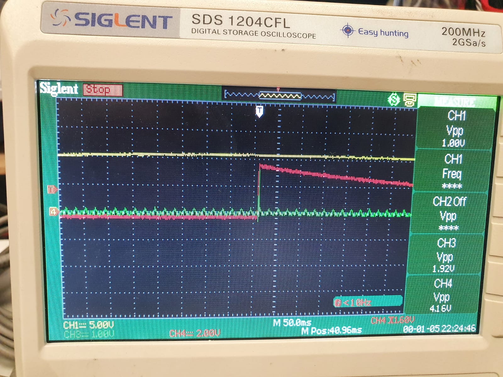
I have designed a 50W flyback converter using UCC28740-Q1 with the 8 output (24V, 250 mA). I am only regulating a single output as I wanted to have an isolated power supply. My transformer has a single auxiliary and 8 secondary winding. I followed one of your TIDA-010000  designed and modified as per my requirement. I have a problem with the continuous operation as this device is kept shutting down. As you can see in this picture, the yellow shows VDD voltage, green shows FB voltage from the Opto and RED shows a single 24 V secondary output. The system is shutting down or resetting before even it reaches to 24V. Currently, I am getting around 8V on the secondary side. 

I would be grateful If you could provide some suggestions to solve this issue.

If you have any questions, please do not hesitate to contact me.

Thanks and regards,

Chirag

  • Hi Chirag,

    Could you please attach your schematic  and transformer turn ratios , windings structure ( stack up figure ) and more waveforms

    the waveforms should tell us , each channel voltage  for example CH4 is output voltage , in the waveform I see each div is 2V , but the maximum is less than 2 divs . that means the output voltage peak value is less than 4V , but you told me is 24V , I was confused .

    And please let me know  the hiccup time , more long time waveforms should been captured . VDD voltage is important .

    Thanks.

  • Hi Jaden, 


    Please find attached a copy of my schematic which was modified from the TIDA01000 design as per my requirements. This flyback converter has 8 secondary windings (24V and 250mA) and an auxiliary winding (12 V, 100mA).  As you requested in the last post, my transformer details are as follows:

    MATERIAL F44

    GAPPED CORE 0.4MM AIRGAPPED (ETD CORE)

    Primary Inductance -3000 uH

    Primary windings (114 turns) ( Layer 1- 43 turns,  Layer 2- 39 turns,  Layer 3- 32 turns)

    Auxiliary winding  (7 turns) ( Layer 4- 7 turns)

    Secondary windingS ( (12 turns PER WINDING) ( Layer 4- S1,  Layer 4 - S2,  Layer 5- S3,  Layer 5- S4,  Layer 5 - S5,  Layer 6- S6, Layer 6- S7,  Layer 6 - S8)

    NOTE: INSULATION TAPE HAS BEEN ADDED BETWEEN WINDINGS TO INCREASE INSULATION.

    PROBLEMS:  In order to do testing, I have just populated only one secondary winding and applied 550VDC. THE three-phase AC voltage circuit is not populated.

    When I applied DC voltage, the secondary voltage reached 8 volts and the converter reset or shut down mode. The secondary voltage never goes above 8 volts. I have added some figures for a better understanding.

    Please note; I have not populated compensation RC on the feedback circuit. I have ONLY populated only one secondary side circuit. 

    Please let me know if you need any more information.

    Thanks and regards,

    Chirag

  • Hi Chirag,

    Some comments after review your design:

    1. The VS pin upper divider resistor should be connected to AUX winding , while in your schematic it connected to the AUX rectifier diode cathode.

    2, what is your input voltage range ? how you got the transfer design ? Could you please down load a design calculator toll from TI.COM website to calculate the parameters and transformer . For example , if the input voltage is 550V , Vout=24V and Iout is 0.25*8=2A , roughly calculate the transformer inductance is ~800uH and Nps turn ratios should be ~26 . But I see you transformer Lm is 3mH , and turn ratios is 9.5.

    Thanks.

  • Hi Chirag,

    Did you applied my suggestion on your board ? any feedback ?

    Thanks.

  • Hi Jaden,

    Thank you for your reply and for checking out. Your first suggestion was identified and modified when I started testing initially. I forgot to make changes to the provided schematic. I did use different methods to calculate the transformer inductance and related parameters. I am going to use your calculator and build another transformer with modifications (any changes on the other components). Please find attached an excel file with my user parameters.  Please ignore secondary side rectifier parameters as I have 8 outputs. 

    Please do not hesitate to contact me if you have any suggestions to improve.

    Thanks and regards,

    Chirag3872.sluc487b.xlsx

  • Hi Chirag,

    I'll reply you on Friday.

  • Hi Chirag,

    Some suggestions for your design as below:

    1. The VS pin 22pF capacitor should be removed since any capacitor on here will cause signal delay .

    2. The maximum desired switching frequency in your calculation tool can be changed from 40khz to 80khz , since the controller can support 100khz , too low frequency means large inductance.

    3. UCC28740 VDD_ON voltage is 21V , but in one of your waveform , the VDD voltage is around 12V when the "start pulse" occur . that is doesn't make sense.

    4. All of protections are descripted on datasheet chapter7.3.4. Could you please check it one by one and capture the responding signals , for example, for Primary overcurrent protection , Please capture the transformer primary winding current or CS pin voltage to see if there is a over current.

    Please let me know if you have further questions.

    Thanks.

  • Hi Chirag,

    Since not get response from you a long time , I believe you have solved this problem. if you have other questions , please create a new post.

    Thanks.

  • Hi Jaden,

    Thank you for checking. I was able to run the converter for a few seconds instead of three pulses now. But I came to understand that my PCB design creates lots of noise which affects other feedback/measuring parameters and forced the converter to go the reset mode. I am in the process of designing a new PCB and will run the converter in a few weeks. 

    Thank you for your feedback and time.

    Thanks and regards,

    Chirag