A related question is a question created from another question. When the related question is created, it will be automatically linked to the original question.
If you have a related question, please click the "Ask a related question" button in the top right corner. The newly created question will be automatically linked to this question.
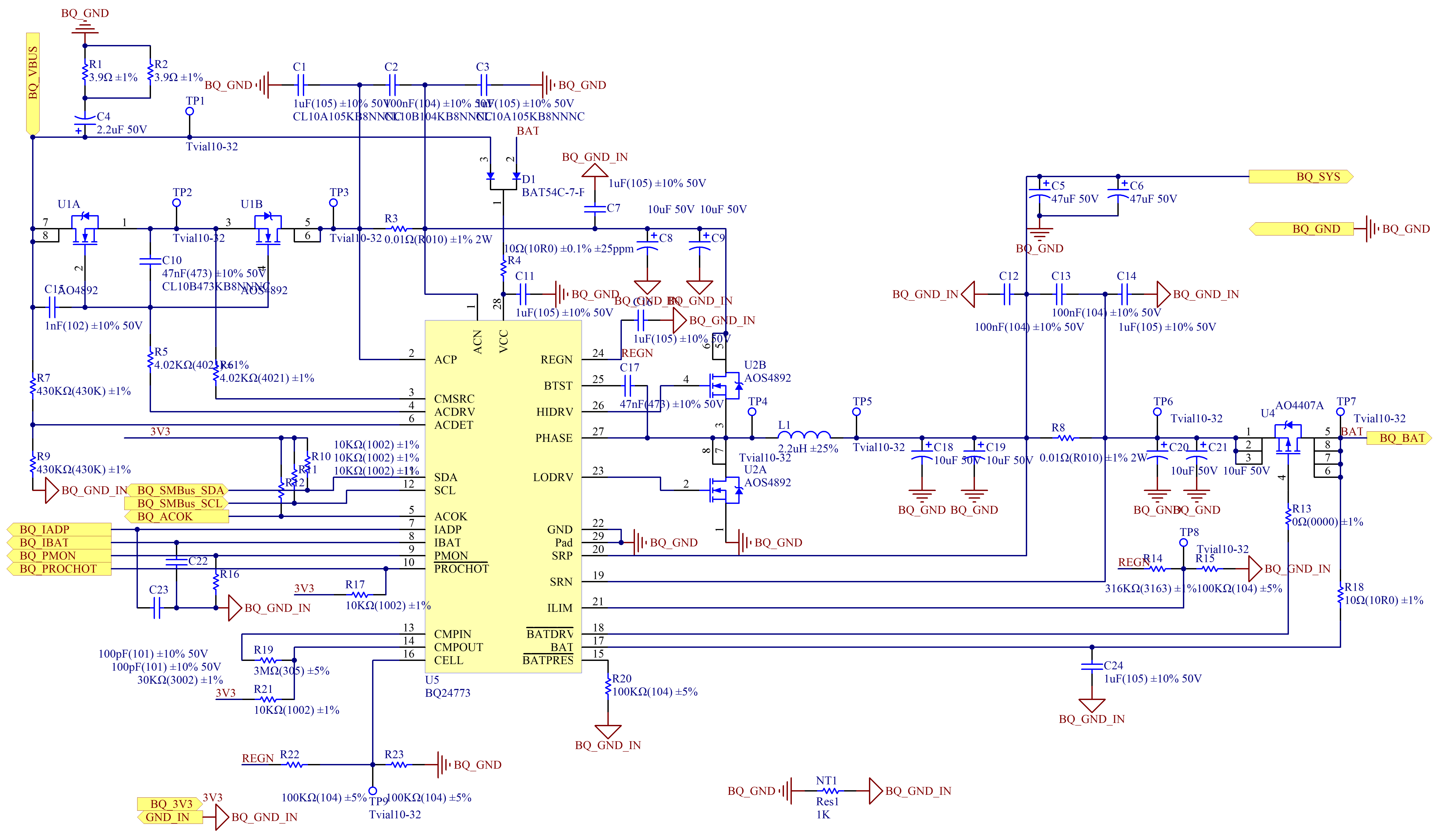
I noticed several things in the schematic that are unusual:
1) What is the adapter voltage (BQ_VBUS)? The ACDET resistor divider is 430 kΩ/430 kΩ, so ACDET is half of the adapter voltage. However, the absolute maximum rating for the ACDET pin is only 7 V. Please let me know the adapter voltage so we can determine the ACDET pin voltage.
2) How many cells is the battery? The CELL pin has a 100 kΩ/100 kΩ resistor divider biased by REGN. Since REGN is 5.4 V, the CELL pin is 2.7 V (logic high), which indicates a 3s or 4s battery.
3) Is the connection between power ground (BQ_GND) and analog ground (BQ_GND_IN) a 1 kΩ resistor, or is it a net tie? Power ground and analog ground should be connected at the thermal pad, as described below:
1, BQ_VBUS is 19V, and the voltage divider resistance has been changed from 430k/430k to 430k/66.5k;
2, The CELL pin is connected to GND;
3, BQ_GND and BQ_GND_IN are connected together through a 0ohm resistor.
4, Register setting as below
BQ24770 BQ24770_REG_ChargeOption0 is 0x634e BQ24770 BQ24770_REG_ChargeOption1 is 0x0a11 BQ24770 BQ24770_REG_ChargeOption2 is 0x0040 BQ24770 BQ24770_REG_ProchotOption0 is 0x4b54 BQ24770 BQ24770_REG_ProchotOption1 is 0x8120 BQ24770 BQ24770_REG_MaxChargeVoltage is 0x1010 BQ24770 BQ24770_REG_MinSystemVoltage is 0x0f00 BQ24770 BQ24770_REG_InputCurrent is 0x0800 BQ24770 BQ24770_REG_ChargeCurrent is 0x0f00
Thanks for making the schematic changes in 1), 2), and 3). Your register settings look fine. Please resend the schematic so I can check the updated version.
First, let's check whether the ACFET and RBFET are turned on. Please use a multimeter to measure the following voltages: BQ_VBUS, ACN, ACDRV, CMSRC, ACDET, and ACOK.
If possible, please use an undamaged board with a new BQ24770 IC for this test. The ACDET resistor divider in the old schematic caused the ACDET voltage to exceed the 7 V absolute maximum rating, so it's possible that this may have damaged the ACDET pin.
Lastly, please note that for 1s applications, we typically recommend one of our dedicated single-cell chargers, such as the BQ2560x family or the BQ2589x family. These chargers allow a simpler, more integrated solution for 1s applications. The BQ24770 can also be used to charge a 1s battery, but this is a more complicated solution, and you also need to verify that the BATFET can be fully turned on, as described below: