This thread has been locked.

If you have a related question, please click the "Ask a related question" button in the top right corner. The newly created question will be automatically linked to this question.

TPS65131: TPS65131

Part Number: TPS65131

Hello!

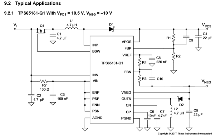
Recently I made a new design which includes the TPS65131. The use case is 5V in (USB) to +/-6V out. The design was based on the Typical Application schematic from the part datasheet, as can be seen below.

The positive output voltage is as expected. On the 3 ordered prototypes the output was -30v on 1, and jumping between -5 and -15v on the other 2 prototypes.

After desoldering the C10 cap, the output voltage is as expected on all the prototypes. This seems to be equivalent to this issue:  

Now I also found the TPS65131EVM User's Guide which contains a schematic which is slightly different from the datasheet:

My main question is, could the added resistor R6 which is in series with the C10 cap (which is c9 in this schematic), solve this issue? If so, perhaps should this be added to the typical application schematic?

For now my issue seems solved by just removing C10 but this doesn't seem optimal.

Thanks in advance

Marco


  • Hello,

    It does appear that the issue you are seeing is due to noise  coupling into the feedback pin (FBN) and in that case adding a resistor in series with feed forward capacitor will help to cut down the noise and stabilize the control loop. Datasheet does recommend that in section 8.2.2.6.1 about feed forward capacitor and i copy the relevant section below.

    ============

    8.2.2.6.1 Feedforward Capacitor
    As a recommendation, to speed up the control loop, place feedforward capacitors in the feedback divider, parallel
    to R1 (boost converter) and R3 (inverting converter). Equation 11 shows how to calculate the appropriate value
    for the boost converter, and Equation 12 for the inverting converter.
    (11)
    (12)
    To avoid coupling noise into the control loop from the feedforward capacitors, the feedforward effect can be
    bandwidth-limited by adding a series resistor. Any value from 10 kΩ to 100 kΩ is suitable. The greater the
    resistance, the lower the noise coupled into the control loop system.

    =========

    Kind Regards,

    Liaqat