This thread has been locked.

If you have a related question, please click the "Ask a related question" button in the top right corner. The newly created question will be automatically linked to this question.

LM66100: LM66100 + TPS22918: Ideal diode with Enable?

Part Number: LM66100
Other Parts Discussed in Thread: TPS22918, TPS2121, TPS2120, TPS2113A, TPS2115A, TPS22912C

HI,

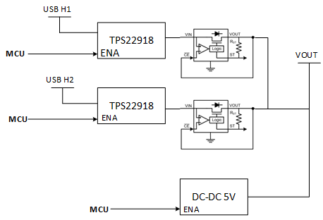
I need to switch between 2x 5V sources at 1A each (not a power sharing application). Looking at all the ICs available, I found that the 2x (TPS22918 + LM66100) seems to do the job:

Can you confirm that it will work if I connect them as described in the previous figure?

This is probably not the smallest solution, but the total cost if very low and Ron is still acceptable for me.

Best Regards, 

Denis Alain, Eng.

  • Hi Denis,

    Your image is not loading, you may need to reupload it and 

    For the purpose of switching between 2 sources, you can use a PMUX to accomplish this job with just one IC, and with a lot more flexibility. You can do automatic or manual switchover between the supplies, or select the threshold. The devices i have recommended below also have current limit

    I would suggest to take a look at 

    TPS2121, TPS2120 -> these have a wider voltage/current range than your spec and have more flexibility, you can prioritize using one input even if its slightly lower than 

    TPS2113A, TPS2115A -> these are 5.5V/1.25A parts with automatic switchover, less feature than above and they are much older parts than TPS212x


    For a full selection of our PMUX products which you can check ,please see here

    And i would highly recommend to take a look at our App report on PMUX which gives some good basic info on using / designing with them. Just know that the comparison table doesn't have all of our parts so its better to look at the PMUX page above for all oru offerings. 


    If this answers your questions please let me know bypressing the green button but do let me know if you have any followup questions.

    Best

    Dimitri

  • Hi Dimitri,

    This is my original picture:

    As you can see (I hope it worked this time), I have 3x sources: 2x from USB host (5V) + 5V from a DC-DC (from TI of course!) with an enable. The DC-DC can work with a pre-biased output, so I connected it directly to the point of load.

    Because I need to have a full control over which source is selected with my MCU (an always powered MCU), the TPS212x cannot work. On TPS212x, you can force IN2 to be selected, but not IN1. Same problem with the TPS2113A: I don't have full control of which input selected with Vsns.

    Looking at your links, I found that the simple TPS22912C can do the job. It has a permanent reverse current protection, it's small and I can copy-paste it to all sources. Unless you have some concerns about it vs my application, I will go with this IC connected in star topology with ON pins connected to my MCU.

    Best Regards, 

    Denis Alain, Eng

  • Denis Alain1 said:

    Because I need to have a full control over which source is selected with my MCU (an always powered MCU), the TPS212x cannot work. On TPS212x, you can force IN2 to be selected, but not IN1. Same problem with the TPS2113A: I don't have full control of which input selected with Vsns.

    Hi. TPS2121 and TPS2120 actually both support manual switchover and eliminate any timing / logic considerations you'd have with 2 seperate load switch.. I would suggest to use either. For this purpose both will functionally be the same. 

    best

    dimitri

  • Hi Dimitri,

    How can I disable both sources with the TPS2120? I will need to disable both inputs, when my DC-DC is ON (powered from an external power supply). The only way I found is by setting SEL > VREF and OV2 > VREF. Since I don't need the overvoltage feature, I guess it could work.

    Also, the section "9.3.6 Fast Reverse Current Blocking (RCB)" talks about the reverse blocking feature when the output is higher than the input. But what will happen if I intentionally disabled both inputs and apply a voltage at the output with my DC-DC? Does the RCB feature will still disconnect the output voltage from the inputs?

    Thanks,
    Denis.

  • Denis,

    Denis Alain1 said:

    How can I disable both sources with the TPS2120? I will need to disable both inputs, when my DC-DC is ON (powered from an external power supply). The only way I found is by setting SEL > VREF and OV2 > VREF. Since I don't need the overvoltage feature, I guess it could work.

    Yes you can do it this way. SEL=0 , OV2>VREF will switch off both inputs .

    Denis Alain1 said:

    Also, the section "9.3.6 Fast Reverse Current Blocking (RCB)" talks about the reverse blocking feature when the output is higher than the input. But what will happen if I intentionally disabled both inputs and apply a voltage at the output with my DC-DC? Does the RCB feature will still disconnect the output voltage from the inputs?

    If the device channel is switched off it will block it as there are back to back fets for each channel. Fast reverse current blockign applies when the channel is ON. If the channel is OFF there is no potential for reverse conduction.

    best

    dimitri

  • It sounds good!

    Thanks Dimitri.