


Other Parts Discussed in Thread: TPS563209
Hi
I'm Gunwoo Ha and I’m working at the VPIX Medical in South Korea.
Our company makes medical equipment and I’m involved in making an embedded system in the medical equipment using your IC, LM27762.
These days, I’m doing trouble shooting our analog system and I have few questions on using LM27762.
Let me describe about the details first.
First of all, we want to get output voltage of +5V and -5V with input voltage of 5.5V. So, we designed schematics as below(Fig. 1).
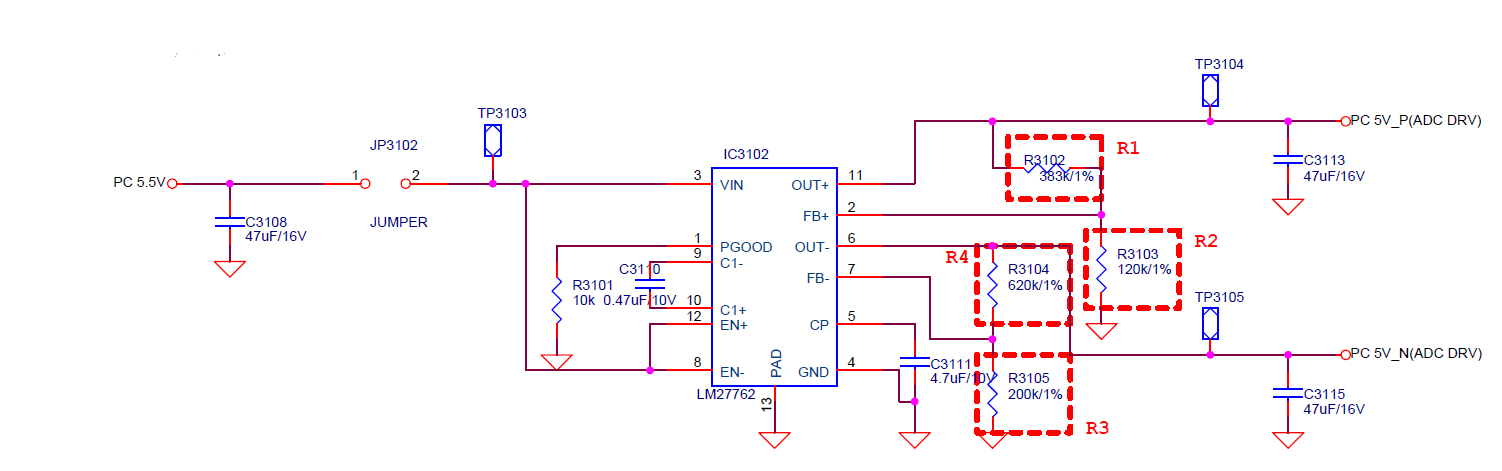
Fig.1 Schematics_New
However, the output voltages are +4.6V and -2.6V (or +0.6V) respectively whenever there is load or not.
I already used same schematics for our previous system as below (Fig. 2) and it worked well.
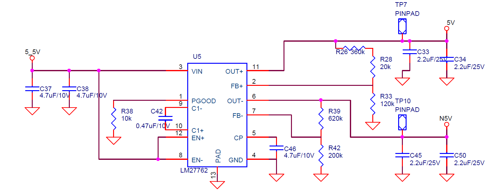
Fig.2 Schematics_Old
The differences between Old and New one are these;
-
Input capacitor value - old:4.7uF x 2, new: 47uF
-
Output capacitor value - old: 2.2uF x 2, new: 47uF, although we’ve changed this same as old one, it still doesn’t work
-
Driving circuit – old:LT3086(Analog Devices), new: TPS563209(TI)
-
# of driven circuit – old: 1(AD8138, Analog Devices), new: 2(Same)
-
Foot print size – slightly smaller than before
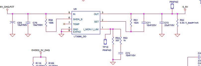
Fig. 3 Driving circuit; Old:LT3086
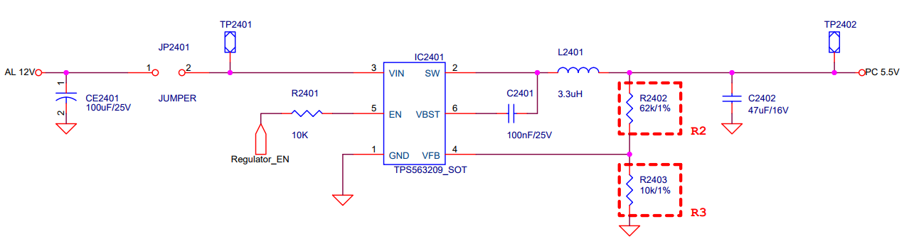
Fig 4. Driving Circuit; New: TPS563209
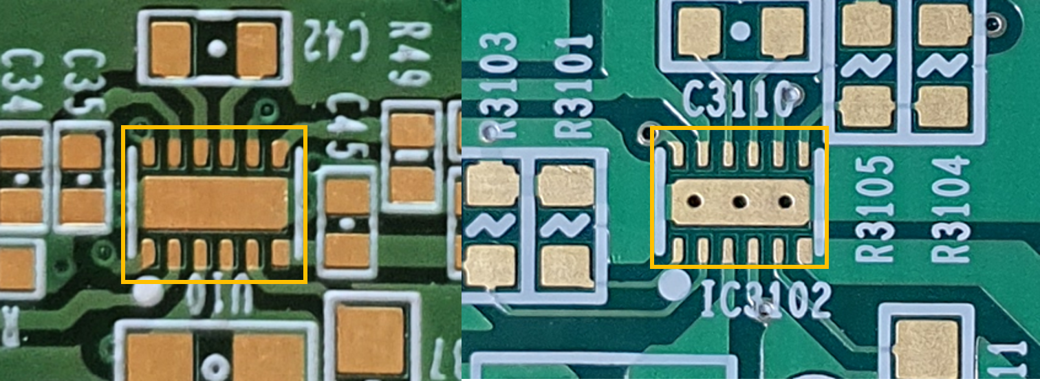
Fig. 5. Foot print
When it is not working well, we checked transient waveform of output and input of LM27762 as below (Fig. 5). Here, transient means that when we apply enable signal to driving circuit.
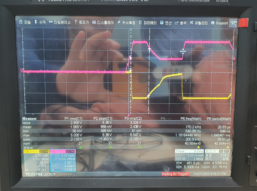
Fig. 6. Transient waveform of LM27762, input(Red) and negative output(yellow)
As you can see from fig.6, the input fluctuates when the negative output fluctuates.
This abnormality is not always happening, but it shows frequently. That’s why we are not able to figure out what the clear cause is.
Do you have any idea about this problem?
Although you may be busy, could you please reply as soon as possible?
Best regards,
Gunwoo Ha (Research Engineer)
VPIX Medical, Inc

