This thread has been locked.

If you have a related question, please click the "Ask a related question" button in the top right corner. The newly created question will be automatically linked to this question.

TPS54202H: outpout ripple

Part Number: TPS54202H

Hi team,

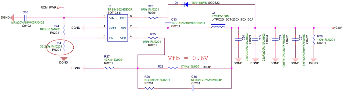
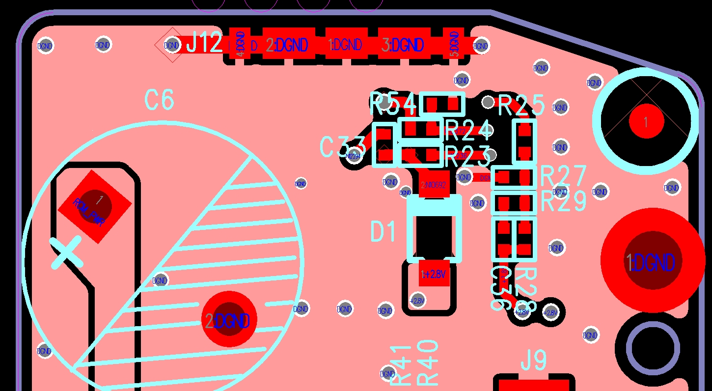
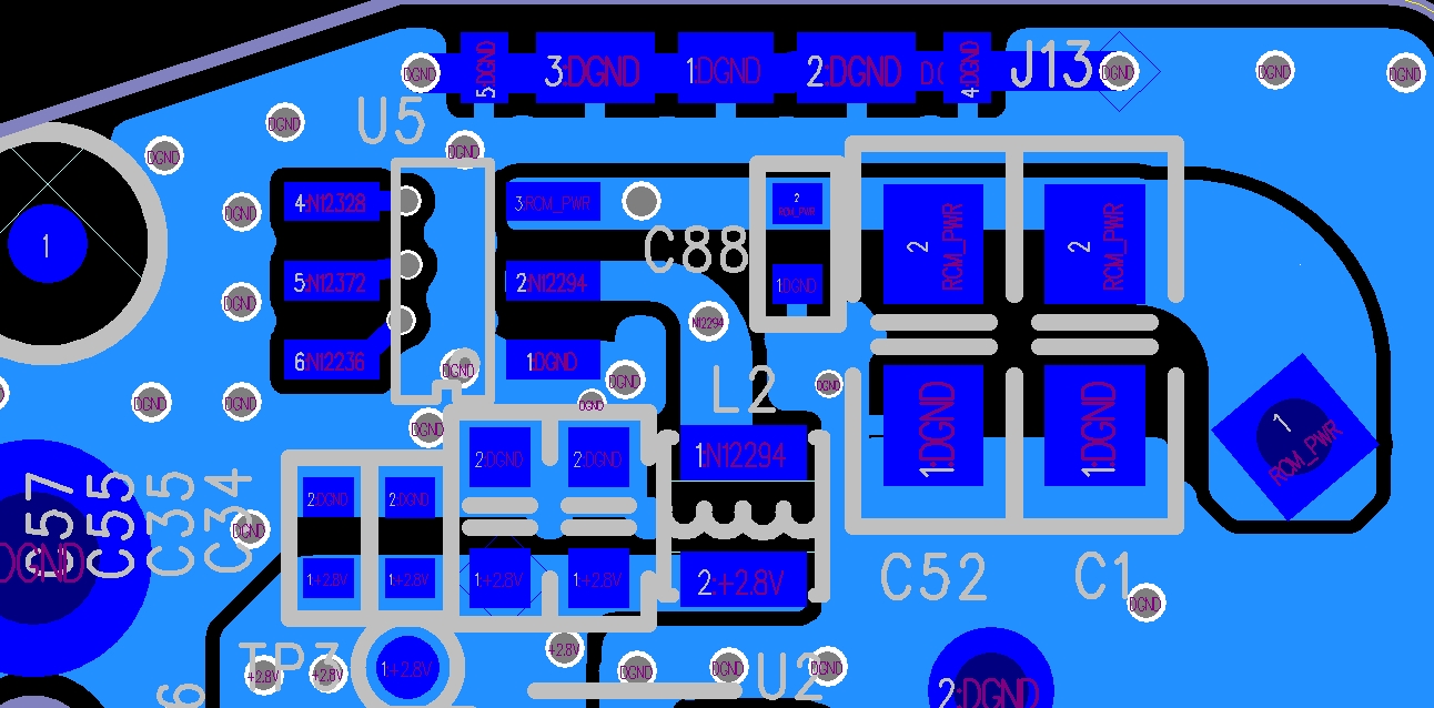
below is customer schematic and layout, their input is 13.5V,output is 2.8V/175mA

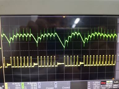
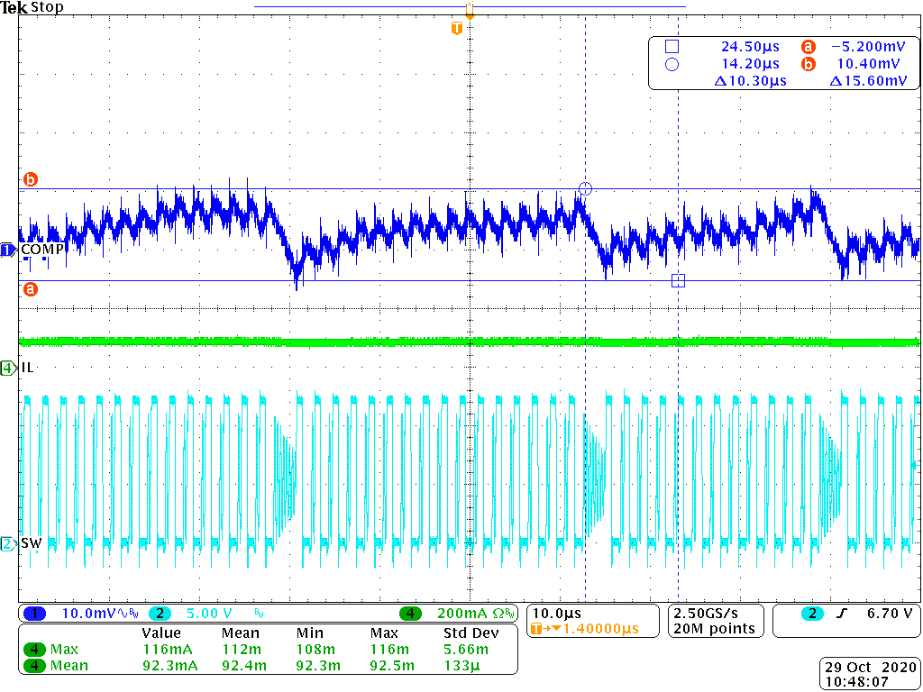
customer found the output ripple is too large which can't meet their requirement. now the output ripple is 50mV, they require ripple should be less than 20mV.

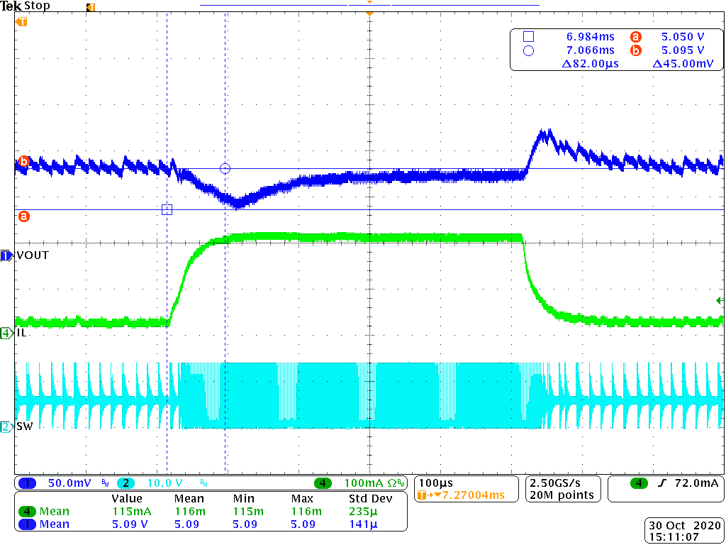
The load is wireless module, it will switch between sleep and work.

I have let customer to change the C36 to 56pF, and change L2 to 4.7uH, but not have help, could you help give some comments?thanks.

  • Hi,

    Could you help try change C33 to 0.1uF and check it again ?

    BRs,

    Young

  • Hi Young,

    C33 is 0.1uF actually. 

  • Hi ,

     From the waveform you attached, I figure it works in ECO mode or HS can't turn on sometimes , resulting in this large ripple.

    and I did some test on EVM board, and find that devices still works in CCM mode(ripple <10mv) and the output ripple still less than 16mv even in ECO mode at lighter load.

    Here is some action may need you help to check.

    1.What's the value of inductor ? please share the PN# .

    2.Remove D1 and check the device still has large ripple or not and also check it is in CCM /ECO mode.

    3.What's the value of R29 ? is it installed on board ? replace it with 0 ohm resistor if yes and then try again.

    4.For the layout, could you help mark the convert and the component out for us to review? Or you can send them to a0223945@ti.com .

    4.Below waveform captured on EVM for your reference .

    CH1: Vout ripple;

    CH2:SW;

    CH4:Iload.

  • Thanks Young.

    1. inductor value is 10uH, PN# you can see in scehamtic

    2. they remove the D2 but not much help.

    3. for R29, they add 0ohm / 100ohm and remove it, but don't get much help. the ripple is around 30mV.

    4. for layout, I will marked and sent to you later.

    one more quesion, I see you test in a stable load current. but In customer applicaiotn, the load current is changed. The load is switch between sleep and work. load current can be change from ~0mA to 175mA.

    thanks

  • Hi,

    One item need to check with you. The waveform attached is dynamitic load ? or what's the load for this waveform ?

    Devices may work in ECO mode and bring in a larger ripple , and I will check on EVM about the load transient then feedback to you the results .

    BRs,

    Young

  • Hi young,

    it works in dynamitc load, the load current is in the range of 1mA~200mA. load is a camera, it is switch between sleep and work

  • Hi,

    If the load is dynamic , it's reasonable that the output ripple is larger .As the load increased, device may take some time as feedback to adjust this change . You can refer below load transient waveform for your reference . SR:1.6A/us.

    You can try to add a large E-CAP at the output , like 220uF or larger. This should work to reduce this ripple. 

    BRs,

    Young