This thread has been locked.

If you have a related question, please click the "Ask a related question" button in the top right corner. The newly created question will be automatically linked to this question.

ISO5852S: Debugging of TIDA-01606_Gate DriverE2: ISO5852S DESAT Function

Part Number: ISO5852S
Other Parts Discussed in Thread: TIDA-01606,

Dear all,

I am trying to create a system to test the gate driver cards E2 which are used on the TIDA-01606 power converter design.

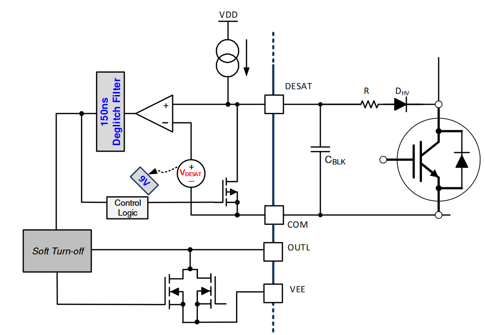
I am having difficulties understanding how the DESAT function of the gate drivers ISO5852S works.

I would like to emulate a fault so that I can assess if the fault/reset function on the gate driver is working properly, however I do not understand what kind of signal I need to apply to the DESAT pin in order to trigger the fault. I have also read that the DESAT function can be configured to trigger the fault at some user defined conditions, however I do not know how to do this since I do not understand how the DESAT function works. 

If anyone has any suggestions or can suggest any reference documents please let me know.

Thank you in advance.

Yours sincerely,

Adriano Arci

  • Hello Adriano,

    Thank you for the interest in the ISO5852S. Our expert on this device is out of the office at the moment but will respond to your questions shortly.

    Regards,

  • Hi Adriano,

    Welcome to E2E!

    The DESAT pin of the ISO5852S has an internal comparator  (9V threshold voltage) and an internal current source. A typical DESAT configuration is shown below:

    During normal operation, with the output high, the diode would be forward biased. With the diode forward biased, the charge on the capacitor CBLK would be limited to the forward voltage of the diode + voltage drop across the resistor. This must be designed to be less than the internal comparator threshold (9V) during normal operation. In the event of a short circuit, the diode will be reverse biased. Once the diode gets reverse biased, the capacitor will begin charge up. Once the capacitor voltage has reached the DESAT threshold (9V) the device will begin its de-glitch filter time after which it will shut down(current source will also turn off).

    If you would like to test the FLT and RST functionality I would recommend injecting a pulse higher than 9V (10V would be enough) for longer than the deglitch filter (230ns max). Once FLT is triggered you will have to wait for the mute timer to expire (1ms max) before applying the low RST pulse to reset the device. The low reset pulse must be longer than the reset deglitch filter(800ns) to properly reset the device.

    Let me know if you have any questions!

    Best regards,

    Andy Robles